
What are
/r/PCB's
favorite Products & Services?
From 3.5 billion Reddit comments
The most popular Products mentioned in /r/PCB:


The most popular reviews in /r/PCB:
I’m confused if you’re asking about learning to solder or actually learning to design the circuits\ If the former: this thing was pretty decent fun
If the latter: check out this course
This is for a dog communication button. I tried googling but can’t find anything.
Thought maybe it’s a flash memory chip?
This is the button.
This is a good one (I own one) and is compatible with Saleae Studio which is free and great. Saleae analyzers are also awesome, but are very expensive.
I basically have this, purchased from another Amazon seller quite a while back. The same can be found on Amazon at higher prices: https://www.amazon.com/Solder-Printer-Screen-Stencil-250X400mm/dp/B07TKVWXTK/
Assuming that it's the same product from the same factory, just white labeled differently, it is a decent balance of price vs performance. I am quite happy with it. Actually, I got a little too carried away using it and am now dialing back how often I used framed stencils, as they do take up a lot of space!
I have used these WS2815 LEDs in the past and they don't have capacitors. At the bottom of sheet 4 of this datasheet there are two ways of connecting the LEDs, I'm assuming the LED strip sold on amazon is using the lower "Complicated Wiring & Space-Saving"?
The recommended application circuit DOES have the capacitors between VCC and GND, but I've never had any issue with the amazon strip. I'm not sure of what the capacitors do, can you explain the pros and cons? Will they have any significant effect on board price if added?
Seems like an overly complicated solution. Would you not still have to solder wire leads to it?
If you do decide to go this route, you'd be much better off using an SMD resistor on the PCB instead of THT.
This is probably the closest thing that exists and you could theoretically cut it into individual pieces. https://www.amazon.com/10pcs-0402-0603-Breakout-Board/dp/B00XSC2730
The board isn’t doing that, your MacBook Pro has a controller that tells the charger brick to switch to 20V. Without a controller IC you can only get 5V, and possibly 0V since the small board is unlikely to have any pull down resistors on the CC lines.
https://www.amazon.com/dp/B0953G14Q2/
These boards have the chip to negotiate the 12V; all you’d need to do is solder the + to your board’s + and GND to GND.
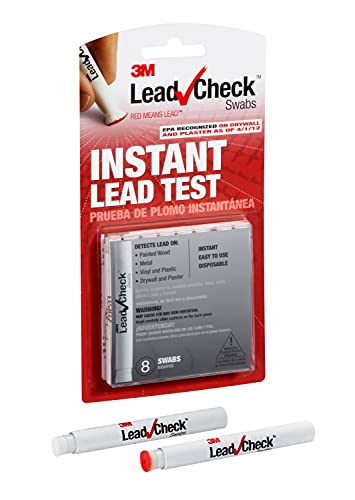
As far as I know, they have no brands. How can I know which one has no lead? I guess I could know it by first purchasing it and then testing with this kind of lead tester, but that will not be very cost effective.
Hey guys, I'm busy with putting my Doom Eternal diorama together and I have a shit load of LEDs to hook together. I know nothing about PCBs or electronics (despite being J-STD certified lol) for that matter, but I know what I'm wanting to do. I'll have about 150 of these LEDs that I want hooked up to one 12 volt power supply. Me not knowing anything about circuit boards, I was wondering if there are any plug and play power distribution boards out there? Any help will be greatly appreciated
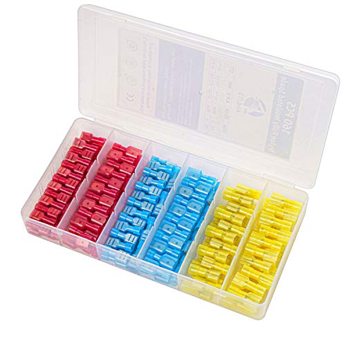
Hi everyone! Thanks for answering my question. I found this is pretty good for the U shape connector, though it is not designed for U shape connector.
You would be surprised, this is actually the 6th option I've tried. So for the design i used this as a guide to make it and just increased the amount of appliances. Also regarding the voltage handling, I would have been using this relay which i think says it is rated for 240V AC, correct me if im wrong
Do you mean how did I come up with the timer circuit? I based it off of a couple different reference schematics I found online as well as the one for the GikFun one that I've been using. I didn't bother with the 5-3.3 step down and added a power led but it is quite similar otherwise. https://www.amazon.ca/dp/B07H3P1NRM/ref=cm_sw_r_cp_apa_fab_ZkrGFb2WHSBK3 Last image is the schematic.
yes, here you can learn how to make the required calculations for any solenoid