
What are
/r/adafruit's
favorite Products & Services?
From 3.5 billion Reddit comments
The most popular Products mentioned in /r/adafruit:


The most popular Services mentioned in /r/adafruit:
Hackster
EduBlocks
Cloudflare
Omni Calculator
The most popular reviews in /r/adafruit:
It might have been MakeCode Arcade. A few more boards like the PyBadge and PyGamer are listed as supported there, Along with appears to be support for the M4 family of boards as well.
A quick search also turned up EduBlocks, a block program editor that supports CircuitPython so in theory should run on most of Adafruit's current boards.
I don't know what they sent you specifically, but those are a couple I am aware of or could quickly find.
Use a Particle Photon board (comes with WiFi capability) and a humidity sensor. There are tutorials online:
Ohh I see where the confusion about the breadboard is coming from now. A breadboard isn’t needed at all. Feathers can be stacked on top of one another like legos. That’s the benefit of the feather ecosystem! You just need to get a set of feather stacking headers with each board purchase. https://www.adafruit.com/product/2830 I have successfully stacked a Bluefruit sense feather on a gps featherwing, rtc featherwing, and tft featherwing. This is known as dual, triple, or quad stacking.
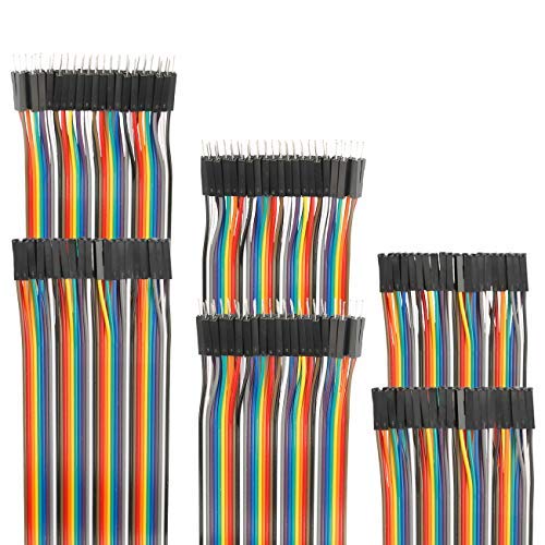
To connect the display to the feather all you need is breadboard jumper wire. Here’s a link to a great kit that has all the different types you might need. https://www.amazon.com/gp/product/B07GD2BWPY
If you can’t find any, the Adafruit’s CAN bus guide states that you can also use Feather STM32F405 Express or Metro ESP32-S2 Express with an external CAN transceiver. The guide has a link at the bottoms of the first page to purchase the CAN Bus Module Transceiver (TJA1050) on Amazon. They are $8.99USD for 5 transceivers.
Why do you even need that? I just use vectorboard (perforated board), cut to whatever size you want. i use that with wirewrap wire and solder.
It's surprising the board can't directly power a small motor https://thepihut.com/products/vibration-motor-11-6x4-6x4-8mm but you're correct I never thought to check until now.
Confused about the TP4056, I thought the whole point of it is to handle pretty exactly my use case, the illustration on Amazon seems to suggest so.
I'll try and wrap my head around those tutorials.
Seems to be working for me... just checked...
But just in case... here is the jist:
Rendering a monochrome glcd bitmap image
I am trying to get a representation of what I am rendering on an 128x64 oled screen (OLED SCREEN) to be presented within a web interface. The LCD images are stored in a monochrome bitmap format. As I understand it, each bit represents a pixel's state... but I am having trouble with actually getting the image drawn correctly.
I've set up an example of what I am trying to achieve with the adafruit's logo; you can see the image is partially rendering correctly... but not perfectly. Does anyone have any ideas on where I've gone wrong?
Codepen Example
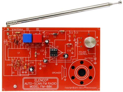
Soldering is a skill in itself. I would start out with a "soldering project kit". It's usually a common device like a radio that you can use afterwards https://www.amazon.com/Elenco-FM-88K-FM-Radio-Kit/dp/B004YHZE0G/
With one of these kits you'll get familiar with some basic concepts and components. If you haven't gotten one already, a cheap (but safe*) multimeter will be required for your journey. https://www.amazon.com/Amprobe-AM-510-Commercial-Residential-Non-Contact/dp/B007FZFTZO
*buyer beware: some of the meters out there are completely unsafe to use on your house's mains.
Well... maybe, maybe not.
What microcontroller are you running? Are you running the Circuit Playground, a Feather, or something else? If you're running the Circuit Playground, you are kind of limited in terms of what you connect because you've got to either use alligator clips or screw terminals. If you're using a Feather, you can either use a CRICKIT, or you could just hit Amazon and get 4 packs of L298N motor drivers and 6 packs of 3-6v TT motors for about $12 per pack, respectively. It's not as neat a form factor as the CPE or anything on a CRICKIT, but it's going to be:
- WAY more cost effective than Adafruit stuff (no offense to Adafruit, they're a fine company).
- More DIY, which if any of your kids become more interested in microcontrollers or hobby electronics, they'll want to become more accustomed to using components like those.
I've done it both ways, actually. I just happened to have a CPE and a CRICKIT laying around, but before I went that route, I used an Arduino Uno and an L289N to drive a pair of TT motors. It was only marginally more difficult to use-- the only real hard part was getting the parts to all mount to the acrylic base. It had mounting holes cut, but none of them fit, so I had to drill some myself. Now, I have a Genmitsu 3018 CNC machine, so next time I want to fool around with a robot car, I'll probably just design and cut the acrylic base myself.
Yea I ended up using these chips that do all the battery management including charging, voltage regulation on the supply side at a constant 5V, under/overvoltage protection, and allow for pass-through charging so you can use the device while your battery charges.
The built-in battery management system on the Huzzah is poorly designed.
I want a USB port with an on/off switch that can be turned on/off by software, so I don't think this would meet my requirements - it looks like this is controlled by physically switching on and off.
That said it's only for one USB device, so I don't want/need a whole hub either. Something like this but with a wire to GPIO (or USB data controlled) for switching on and off instead of a physical switch is what I am looking for.
What’s the device? Is it something you could have the Raspberry Pi activate / deactivate?
There’s a lot of smart switches out there in both power outlet and USB varieties that you can toggle with an app or smart assistant. https://www.amazon.com/Adaptor-Devices-Compatible-Assistant-Required/dp/B087LTP9KN
Cutting power inline to something like a webcam might be more difficult.
I have a similar set up and the electrician put in led driver like this one:
I am not home so can't see the particular brand but this looks like the same thing he used.
Basically you would need sth like this:
https://www.amazon.de//dp/B07S528L6C/
where you set the output voltage to 3V and connect the 2 power lines of the backlight to the +/- load screw terminals
Instead of looking at closing vents, have you looked at boosting? e.g. https://www.amazon.com/AC-Infinity-Register-Thermostat-Control/dp/B0792R5KJF
The reason I ask this, it is generally a bad idea to close vents. When your system was spec'd out it assumes all vents will be open. Closing more than one or two can build up pressure in the system and a) cause motor strain b) in your aged system, it will cause conditioned air to leak out of ductwork and c) can push ducts off their outputs (and you've already experienced this, so your risk is higher).
One thing I could find is this, which has even lower stickout, requires soldering, and leaves it up to you to figure out the other end of the "cable".
I also had some maybe luck searching for USB-C ribbon cable or USB-C flat flexible cable (FFC), which gets me things like this which is USB 2 only and goes from USB C to USB A. I did find some similar FFCs that go from USB C 3.1 to USB C 3.1 but they aren't right-angle connectors.
But I think if it exists, with those search terms you can find it just as well as I can.
This is where I was kinda hoping there was a really compact and simple control board that would allow me a more dynamic prop.
As I said above, the tea light idea was where my mind first went. It is basically already wired to do exactly the effect I'm looking for, except for having to wire up multiple LEDs.
The only real issue I found is that the LEDs in those lights look to be 3, maybe 5mm. They are pretty tall and so I start running out of space pretty quick unless I start sanding off the rounded top.
https://www.amazon.ca/EDGELEC-Flickering-Flicking-Emitting-Resistors/dp/B0785DQ8FD?th=1
Using some kind of magic I don't understand, I think these are how the tea lights work. They don't appear to actually be driven by an external board, but somehow flicker on their own.
They also come in yellow
Hall sensor
That’s the sensor you want to detect the magnetic field
10Pcs A1302 Ratiometric Linear Hall Effect Sensors Chip https://www.amazon.com/dp/B07DWXCTFL/
I think you could do it just with that and a battery, but I’m not quite that good
Also the sensors do have a direction to them, so you may need to test and research to find the right one.
What kind of usb power supply did you try? I'm no expert but it might be from the power supply being too noisy with interference. You might want to try getting a power supply with a noise filter like this one. Ive heard of similar issues and that switching to a higher quality power supply did help.
Edit: looking at the reviews for that supply have me questioning if that one really does have noise filtering as is claimed. So maybe this one isnt a good option, but maybe another noise filtering power supply might be good.
BINZET DC Converter Step Down Regulator 5V Regulated Power Supplies Transformer Converter (5V 10A 50W) https://www.amazon.com/dp/B00J3MHTYG/ref=cm_sw_r_cp_api_i_2mRyFbGHH8EF2
It mentions automotive in applications. I suppose below 8v minimum input during crank it is dropping below 5v but not low enough to consider a full power off.
LEDs will be much cheaper and more controllable for the same amount of light output, as well as being quite a bit more power efficient, which will help with battery life.
I doubt weight would be a problem, but getting good subsurface scattering will be. If you want the stuffed animal to glow evenly rather than having glowing dots where each LED is, you will need a way to disperse and scatter the light from the LEDs so it looks more like this:
https://www.amazon.com/Creative-Inductive-Stuffed-Animals-Colorful/dp/B073R75ZQD
And less like this:
If you are just starting out with these kinds of project you may be better off looking for something close to what you want and modifying it. For example, this wireless doorbell on Amazon could be modified to fit in the helmet. get two of them and make one for warn and one for penalties.
I would guess you would need to pull the circuit board, extend the battery pack wires to a safe location (maybe a pocket). You might just be able to get an armband jogging holder for a phone and put the receivers on each arm with the left for warning and the right for a penalty for example. I know roller derby can be rough so it would need to be solidly attached.
Could I get 3 of these: https://www.amazon.com/Channel-Driver-interface-PCA9685-arduino-Raspberry/dp/B01D9VNXEQ/ref=sr_1_3?s=electronics&ie=UTF8&qid=1521743412&sr=1-3&keywords=16+channel+pwm
Also any suggestions on which Arduino to get, I see there is the Mega and Leonardo.
Great! So I will go with those or equivalent, I can handle power and wiring etc. on my own. Now, let's talk microcontrolers if I wanted them to be able to be switched on and off, and between modes, from a LAN/Internet device and/or direct connection (pref USB), what is my best bet? An Arduino+WiFi shield, Pi w/ USB wifi adapter I already have, or a trinket/feather/(insert microcontroller here)? Edit: Heres another strand, since I want 30/meter instead of 60. https://www.amazon.com/240pixels-programmable-Individually-addressable-Waterproof/dp/B00K7UHPEC/
Will any code for NeoPixels will work on the respective LED, and/or vice versa? Edit: Heres some I found on Amazon, https://www.amazon.com/240pixels-programmable-Individually-addressable-Waterproof/dp/B00K7UHPEC/ .
Thank you very much for the detailed and great explanation. You absolutely correct, except I am making a rechargeable track IR clip. I want it rechargeable but stable, I also want to be able to run it off a USB in case the battery dies.
To clarify, how much faster will the battery drain at 5v vs 3.3v ~ 3.7v?
Now the powerboost seems like a simple and yet expensive board. How is it different than this? Or does it have a regulated constant 3.3v out vs the adafruits is unregulated? Would this be essencially the same as Adafruit 1904?
Also, I was going to run the LED in a series. Is there any benefit in going parallel?
EDIT: Again, thank you very much for great help.