
What are
/r/raspberrypipico's
favorite Products & Services?
From 3.5 billion Reddit comments
The most popular Products mentioned in /r/raspberrypipico:


The most popular Services mentioned in /r/raspberrypipico:
Hackster
freeCodeCamp
PlatformIO
Let's Encrypt
The most popular reviews in /r/raspberrypipico:
The Teensy 4.0 has a ARM Cortex-M7 processor running at 600 MHz, whereas the pico has two ARM Cortex-M0 processors at 133 MHz (though supposedly overclockable to 400 MHz). So the Teensy is quite a bit faster I’d say. Probably uses more power too.
Thanks so much for this thorough answer.
They aren't super efficient, but you usually don't care if you're charging from USB power or similar. You can also get switching chargers instead. And if you'd rather just spend more money and make it easier, there are off the shelf solutions for this that have the switching logic, BMS, and a spring loaded battery holder for a 18650.
I ended buying this:
https://www.amazon.co.uk/gp/product/B08HQFQT65
with a 18650s parallel battery holder.
From my understanding this setup does it all.
The sleep mode will be the problem. Since nobody has commented yet it might be that you might be the first one trying it. I've had good luck with those I link below but I'm not trying to keep it going during sleep mode. Try a few different ones and report back how it goes I guess.
Running a webserver on one Pico W and doing a simple request on the other should do the trick.
Can easily be done in MicroPython.
Shameless plug
Background...I am working on a timer/LED/buzzer circuit for my son's BattleBots Arena Max that uses a 3xAAA power supply to run a motor driven auger/cheese grater. I want to have my timer circuit also control this motor assembly. Starting the timer script will flash a few lights, make a few tones on a buzzer, then power a relay to start the motor for the auger. When the timer is up, LEDs will change, buzzers will make tones and the auger will stop.
I want this to all have one MicroUSB input, where the relay will be controlled by the Pico W, and still have enough current to continue the script. The power would come into this contraption using one of these and some power would go to the relay, waiting to be controlled by the pi. Power would also go to the Pico, but on which VBUS or VSYS pin and would this work?
Yeah, I feel that too, 3d printer might make it easier, but printed objects are not water tight.
I used this for outside projects (in the shade and under a roof to avoid moisture, should be watertight but you never know): https://www.amazon.nl/gp/product/B09JYYBMC8/ref=ppx_yo_dt_b_asin_title_o01_s00?ie=UTF8&psc=1
If you do find any nice enclosures or way to make them I'm also curious :)
You could, a few options I can think of:
- Have your irrigation system on a local LAN and just expose APIs as you did.
Have pi zero w be the control logic since it has 512+MB of ram and can do a lot more. It will just call HTTP endpoints on your pico whenever someone external wants to. You can just write your python telegram bot or anything else in your preferred language (python is really nice, set up an inline keyboard and send commands via button presses). I'm using rust for fun there.
This is what I did here: https://old.reddit.com/r/raspberrypipico/comments/x5rug1/pico_433mhz_receivertransmitter/
The pico is just a http endpoint that anyone can call, and I have a separate app that I can improve as I wish on a pi4.
- Use pi zero w directly with what you have in place of pico
you just need jumper wires and a breadboard and set up pins as required by board: https://www.amazon.nl/-/en/dp/B078JGQKWP/ref=d_pd_sbs_sccl_2_3/262-1738212-2381938?content-id=amzn1.sym.0714c06f-65f9-4656-a714-9248e17a7eed&psc=1
- Continue using pico, only hurdle is getting a https library in micropython, haven't tried, perhaps one is built in via mbedtls.
After that it's just a set of requests to telegram based on their API, you only need a few endpoints to send and receive commands.
This is the more fun approach, I'll update once I have something for myself. (trying to build a USB keyboard via HTTP)
If you have wall sockets or extensions with USB then it's really easy. (some ideas below)
Alternative is to just use USB ports of routers, most come with some nowadays and I never found a better use case for them.
I'd also use cables without data cables to avoid any unpleasantness if someone wanted to take over your pico via router :)
Found an alternative on Amazon to your link, since shipping will be ridiculous to the US.
For anyone in the future: Link
There’s an mp3 module that’s unbelievably cheap (like cheaper than the pico). It looks like this. I’m not saying to get this one. Just showing you what it looks like. I had this plus a pico and a matrix key pad set up to play MP3s very easily. Your not exactly playing the music off the pico. More like using the pico to process the buttons and send signals to the pins on the MP3 player. In fact, with the right set up, you can just drive some on the pins low manually to skip tracks etc, but it worked really well for me to have the pico as the C3 unit (command control and communications) . I used it to play different stories from a “story box” I made for my kids, so I only have a regular speaker, but I don’t see why you couldn’t just have a headphones Jack or even a Bluetooth module as part of the system.
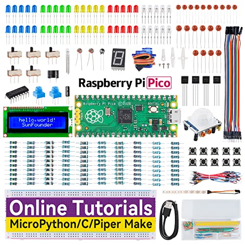
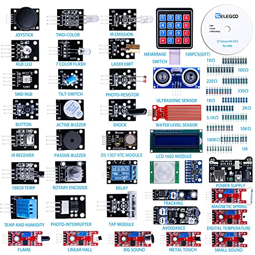
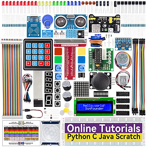
That's a good one I'm looking at this one when payday comes this kitI want for the sero RFID and the stepper motor driver a few things I'd like to learn about
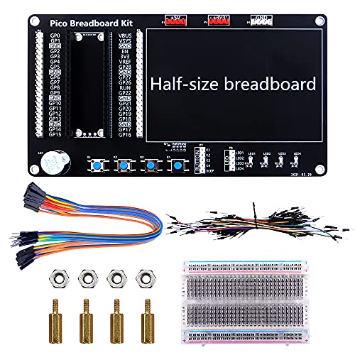
I had bought 2 of these kits, comes with alot of useful bits... Pi Pico Starter Kit thinking I might buy a third so I can have the spare Picos for future projects...
As others have said, an ESP32 is a very capable microcontroller in its own right and using one as a simple wi-fi module for a Pico is a bit overkill IMO.
If you’re needing to add WiFi connectivity to a Pico (or anything with a UART) a cheap ESP01 module like one of these https://www.amazon.co.uk/DollaTek-ESP8266-Serial-Wireless-Transceiver/dp/B07DJ3QMJG/ref=mp_s_a_1_3?crid=2PA8NI5MNT7UP&keywords=esp01&qid=1651868655&sprefix=esp01%2Caps%2C124&sr=8-3 is really all you need. Interfacing is easy; there are lots of resources online about using one of these to wifi enable picos, arduinos and all kinds of other controller boards.
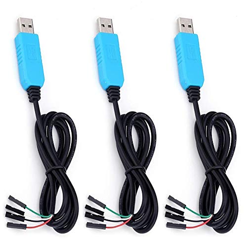
If you have a USB hub, why not just get a USB to TTL serial cable like this one:
The logic levels are compatible so you'd just connect the cable to the chosen UART's TX, RX, and GND pins directly (flipping them of course TX->RX and vice-versa) and then opening another serial terminal using PuTTY or another terminal app.
Thanks, I found this: whiteeeen pi pico Breakout Terminal 3.81 for Raspberry pi pico Board… (2 pcs) https://www.amazon.com/dp/B09HC1BSGS/ref=cm_sw_r_apan_i_DZRF1GNX6YWJ98280442 but they sent the wrong parts. The replacements are on the way and if they mess that up too, I will most certainly get one of your recommendations.
For anyone arriving here with the same issue (I had this too) you can follow the suggestion at https://github.com/thonny/thonny/issues/1986#issuecomment-934771923 and download the LetsEncrypt cert needed at https://letsencrypt.org/certs/lets-encrypt-r3.der
I found the address:
I2C addresses found: ['0x27']
I also imported displayio, but i dont know how to define the display bus with it, im not sure if the display im using is made for dispayio because this is what im using.
any idea how to define it?
I had a look at your non-working code and one thing I noticed is that you're setting the baudrate to 400000 which seems a bit low for SPI.
Maybe try setting it to 1000 * 1000 (1MHz)?
Also it seems to me you're still using the I2C pin numbers but should connect the cables to the SPI ones.
If you have a look at the RPI Pico Pinout diagram you'll notice that I2C connections are colored blue and SPI in a rose color.
I'd suggest you to try connect like the following:
MISO - GP4/SPI0 RX (pin 6)
CS - GP5/SPI0 CS (pin 7)
CLK - GP6/SPI0 SCK (pin 9)
MOSI - GP7/SPI0 TX (pin 10)
RESET - GP8 (pin 11)
DC - GP9 (pin 12)
I've been working recently on connecting to a e-paper module per SPI (unfortunately in C and not in MicroPython), and struggled too a bit first, so those are the things that stand out to me when I look at your code.
Also if you don't have one already you may be interested in a Logic Analyzer device like this one - https://www.amazon.com/AZDelivery-%E2%AD%90%E2%AD%90%E2%AD%90%E2%AD%90%E2%AD%90-Logic-Analyzer-24MHz/dp/B07F8C1PMQ.
It's a handy device for seeing what the communication between the Pico and your modules look like and it's great for troubleshooting.