
What are
/r/Esphome's
favorite Products & Services?
From 3.5 billion Reddit comments
The most popular Products mentioned in /r/Esphome:


The most popular Services mentioned in /r/Esphome:
The most popular reviews in /r/Esphome:
We manufactured these for a project and decided to make them available on Amazon since we couldn't find them anywhere. Check them out: 19mm Latching 19mm Momentary
It's not esphome based, but I just installed an iammeter whole home monitor. The upside is that the devs are really keen on open source, they support local MQTT and modbus access and have a native Home Assistant integration. They're limited to measuring 3 circuits/phases so not per-breaker but you can at least get whole home energy.
You can also look at https://openenergymonitor.org/ . The unit that goes in the electrical box is ESP8266-based, so if you don't want to use their software you might be able to get it running in esphome.
I appreciate your help! I have a second relay because I'm intending on building the same thing for my other garage door, I haven't yet for hopefully obvious reasons :-)
I put the multimeter on all the terminals on both sides of the relay, there's nothing that indicates the ground is connected to the common. I checked +/-/sig against everything on the relay side (NO, COM, NC) for both voltage as well as continuity, the only thing that showed continuity was between COM and NC, which is to be expected. I did the same test on the relay that's installed, same result.
It'll take a minute to disconnect the relay from the ESP because I've gotta take it out of the box, that'll take me a few minutes. I suppose an equally valid test would be to take the spare relay and connect it to the motor terminals, but in case I have a bad relay module I'll do the test as you recommended.
The relay is https://www.amazon.com/dp/B00LW15A4W
I know you already found the problem but I had already pullout out my sensor and hooked it up for testing. I was interested by your phone interference statement but could not reproduce.
I tried recording audio using my default Android Recorder app and it worked; showing signal from sensor every 3 seconds. So that is a good way to test if its working.
https://play.google.com/store/apps/details?id=com.bobwen.xiaojin.bluebatterymanagerbesen using BLE scanner I get this: 020106030200FA06093137343237000000000000000000000000000000000007FF010203040506 but i have no idea if that is usefull data or just a general beacon for discovery
I'm late to the party, but I have DeWalt heater jacket that has a little clip-on connector that attaches to the battery. It provides 20V to the jacket, via a small barrel plug and has a USB port so you can charge your phone, providing 5V. It looks very similar to this: https://www.amazon.com/DEWALT-DCB090-12V-Power-Source/dp/B00EYSUK7W
Unfortunately for this particular board , the Micro USB port is for power. (I have the same switch)
https://www.amazon.com/gp/product/B07S7YNN3S/ref=ppx_yo_dt_b_search_asin_title?ie=UTF8&psc=1
In addition to what everyone else has said, you can probably avoid having to modify the switcher at all.
If your switcher is like mine, that Micro USB port is for an external remote. On my switcher, each pin on the Micro USB plug traces back to one of the tactile switches and there's a common ground. The tactile switch and external remote just short a trace to ground to signal the switcher to switch.
Grab a multi-meter and set it to continuity test, and see if you can identify which pins on the Micro USB port map back to the tactile switch. If it works like mine, you can just cut up a Micro USB plug to make your own external remote using the ESP.
I am not sure the exact model I got, but here is something similar on amazon. Just get any 5v laser diode. I haven't done this yet to mine, but I would also recommend coming up with maybe a 3d printed mount so you can dial in the location of the laser. I got lucky when I stuck it to the roof of my garage and it hits a certain spot of the dash of my car. https://www.amazon.com/20pcs-650nm-Laser-Diode-Diameter/dp/B088PQQ9XV/
Here is the log file with it set to VERY_VERBOSE. There is nothing regarding i2c. I think I am going to just order this board with a built in display and according to the reviews works with ESPhome just fine. The review even gives the config they used to get it working.
esphome:
name: any name here
platform: ESP32
board: heltec_wifi_kit_32
i2c:
scl: 15
sda: 4
display:
platform: ssd1306_i2c
model: “SSD1306 128x64”
reset_pin: 16
address: 0x3C
​
I ordered this power strip that looks identical (except black) a couple months ago and it had an ESP in it. I guess maybe it's hit-or-miss with if they have an ESP or not.
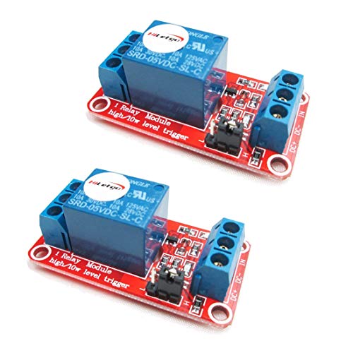
>yet I've seen some people documenting 5V trigger relays in their projects
Those are probably opto isolated relay modules that use 5V for power but the trigger voltage and amperage is much lower.
If you want to use your relay then you will need to step up the voltage. A level shifter is good if you are doing mutiple GPIO 5V outputs. Otherwise you can use a transistor and some resistors.
BTW I added Amazon links just as examples. I do not recommend buying from them due to quality control.
I appreciate the advice! I might do that once I have more of a plan. I did an extension cable for it on Amazon that I planned to cut but I bet that they might know a better way. https://www.amazon.com/Poyiccot-Connector-9-8feet-Extension-Digital/dp/B098JWKBDN/ref=sr_1_5?crid=2X4DL7FC4ZJMT&keywords=4+pin+din+connector+female&qid=1656399900&sprefix=4+pin+din+connector+female%2Caps%2C69&sr=8-5
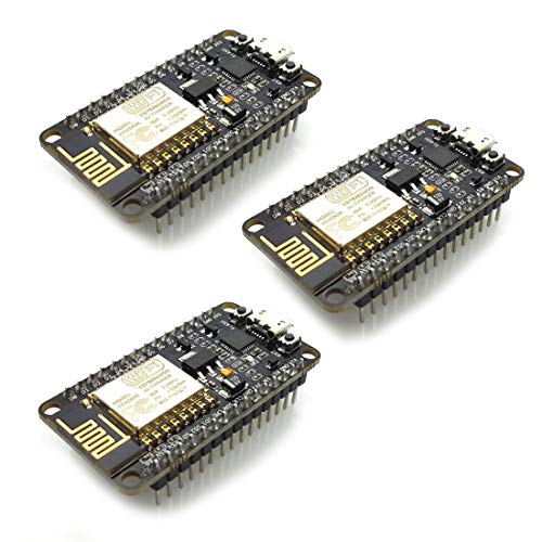
In Germany we get these clones:
AZDelivery 3 x D1 Mini NodeMcu mit ESP8266-12F
Looks the same to me as the D1 mini
5V USB power supply from the wall to power the ESP8266 and the light via a relay. Get an ESP8266 board and a relay or Sold State Relay (SSR) module.
This would work https://smile.amazon.com/HiLetgo-ESP8266-Module-Control-Automation/dp/B071LMSLRW?sa-no-redirect=1 (I've not used this specific one).
Thank you for the reply!
Pretty soon after my post I gave up and set the switches aside for another time when I built up enough motivation to try again. My last attempt was using a serial adapter I had for communicating with VFDs and PLCs, with no luck. It was this one: https://www.amazon.com/USB-RS232-TTL-Industrial-Protection/dp/B07L2VLY5D/
I just ordered the Moyina adapter, will keep you posted later this week!
Maybe more like this one…. https://www.amazon.com/dp/B07MB1J43W?ref_=cm_sw_r_cp_ud_dp_Y2Y0GM8CED0WPBTPTZNC
Have the probe stick out of the box…. Preferably downwards where it will be shaded from direct sunlight, etc.
I did the same exact thing on my first build with a DHT, it reads about 8F too high.
If you don't have access to a 3d printer to make something, you could use something like this, and give your sensor some space from the ESP. I would hang it as far below the ESP as possible so that you are getting a true air temperature reading. Right now, you are measuring the temperature inside the box.
​
dht22 is the kind I have so only 3 pins there so still it gets treated with the same resistor or something else?
I tried a few methods to make this work and came up with something different.
Depends on your washer if this will work, but mine have lights that go off when it stops.
I use a light sensor taped to one of the LED's on the front of the machine (I tried to tap into the internals, but they weren't as digital as i had hoped).
ESp32 with ESPHome detects the light. If it's on - set the binary sensor active. I have one esp32 with light sensors attached to the washer and the dryer.
I used node red to make some automations, but the built in Home assistant automations are good enough now to manage it. Basically, if it's on for more that 5 minutes, assume it's in a wash/dry cycle. When the light goes off, it's done. I then flash some lights in my house. I used to have it play a notification through alexa, but that was annoying.
Anyway, that's just how I did it. Dealing with some sort of analog sensor (motion, sound, etc) seemed like it would require too much tuning to get working right.
That is actually a very nice product, which I have never used before. For something simple like this I would solder everything or use something like https://www.amazon.com/Terminal-Connector-Electric-Barrier-12-Position/dp/B08NGBQWWT/ .
If you decide to run the power to the sensors directly, just make sure they all share a common ground (which they should with the product).
Personally, I would just power the NodeMCU via micro USB and connect the sensors directly to the the board.
Sorry, I may have used the wrong wording. Definitely new to all of this. This is the product I’m talking about. This seemed better than wiring everything straight to the screw terminals of the power supply and I figured I would 3D print an enclosure for this.
I appreciate the reply but I do have some that are only 3 pin, and operate on 5v. These are the ones I have.
Unsure of good brands on amazon as I don't use it, but maybe https://smile.amazon.com/HiLetgo-Channel-optocoupler-Support-Trigger/dp/B00LW15A4W
I have purchased HiLetgo stuff before and it worked fine.
You would only need one relay and just wire the fans together in parallel.
Thank for sharing this build. My very first home automation project was this, but before I started with home assistant. I used a standalone board which isn't easy to configure and is a bit blind https://smile.amazon.co.uk/dp/B07YCGYHLV/
Have been meaning to work out how to replace it with an esp board and make it smarter. Your method seems great, will defiantly try it out. Thanks
>https://smile.amazon.com/gp/product/B07TS3GPQ1 I use this isolated USB to Serial adapter to monitor devices powered by 120v.
Looks interesting! I've ordered one. With any luck I'll get it in 2 - 6 months, assuming it's not stolen (Yeah, we have a problem with our post office here).
​
>Try turning down the wifi power. Default of 20 is too high. Tasmota defaults to 17. See output_power setting here: https://esphome.io/components/wifi.html
Didn't work :(
I'm busy trying to build a tiny Faraday cage to test for EMI/EMC.
I bought an assortment kit on Amazon, it's been handy to have. The ESP32-Dev board fits on the 2 largest sizes in the kit. There are surely other ones with larger boardsif you need. This one is 50 pcs for $15. https://www.amazon.com/gp/product/B07TVHQQ7X/
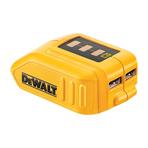
I’d look at something like this to handle the connection to the battery and both 5v and 12v output: https://www.amazon.com/Dewalt-Adapter-Converter-Output-Battery/dp/B08GZ5M3YW
The 12v connection can power your LED strip and the 5v USB will run your ESP8266.
Also, rather than a reed switch you can connect a cheap motion sensor to your ESP8266. Opening the closet door will trigger the motion sensor and you can use that to programmatically turn on (and keep on) the closet light.
Btw, you know about esphome for programming the ESP8266, right?
This ESP with this sensor.
Trigger on GPIO12, echo on 13, voltage is on VCC/5v. I purchased some 20/4 security wire off of Amazon for it so I could have the ESP above my stove in the kitchen with the wire snaking around to the corner of my cabinets for the sensor. I've also got a second one set up exactly the same in my basement for my water softener.
I said 0.1m accuracy above, but it's better than that. Water softener is the only one I monitor consistently, but it's always stayed within ±0.01m.
I use this with an ADC, but it took forever to figure out the wiring as it is not a data pin but a 4-20ma reading.
Which USB stick do you have? I've been using the HUSBZB01 https://www.amazon.com/gp/product/B01GJ826F8 and running 4 of those dimmer switches and not a single issue. No timeouts, no drop outs, never had to re-add them. Been running it for about six months and at the moment I won't buy any other dimmer except those. My friend has some Zooz and they are quite flaky.
I have tried with a Lolin32 Lite and a Arduino mic but it was not reliable enough, I suspect it was the mic that was the problem.
I am thinking of buying a MAX9814 mic as a read that it is working fine with lower sounds but I have not seen any instructions on how to wire it.
Or perhaps something like this: http://amzn.com/dp/B07Y4RBR4J (a light socket to outlet adapter. There may not be enough room in the fixture for this, but something similar could work in regards to the previous response.
Assuming you are using WS2811 LEDs, yes, but you will need a logic level converter because 3.3V is too low. E.g. https://www.amazon.com/gp/product/B0148BLZGE/ref=ppx_yo_dt_b_asin_title_o04_s02?ie=UTF8&psc=1
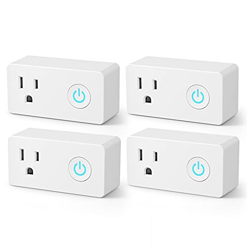
These are flashable using Tuya-convert.
TOPGREENER Smart Mini Wi-Fi Plug with Energy Monitoring, Mini Smart Outlet, Control Lights and Appliances from Anywhere, No Hub Required, Works with Alexa and Google Assistant, TGWF115PQM, 2-Pack https://www.amazon.com/dp/B07D8ZVJN2/ref=cm_sw_r_cp_api_glt_fabc_B11G47QDBEQ9BDXEFFA6?_encoding=UTF8&psc=1
For a full list of supported Dev boards, see here. Filter by Espressif 32 platform.
There's also many more dev boards, chips and modules listed here, though they may not necessarily have platformio IDs.
If your board uses the same ESP-WROOM-32 module, then it will probably also work with esp32dev, though as another person pointed out, you can override board settings.
I use one of these BLE monitoris ( or another generic ) in my car. It'd be great if there was an ESPHome bridge for it, that can live off of wall power in the garage. Others think so too. With that monitor, you have basically no battery impact.
I'm going to be selling BR30 bulbs with ESPHome in the next couple of weeks. My A21s are here and the BR30s are basically the same circuitry in a different form factor: https://www.amazon.com/dp/B09D6HR559
What is needed for xlights in ESPHome? Just the e1.31 effect? I can see about including that by default.
Can you send me a link to the one you use?
Is it this one? I had one, but I hate that it literally takes 5+ minutes to clear. I do have zigbee a wave ready to go sensor
That seems like overkill for just injecting POE. have you considered something like this?
PoE Texas POE-8-24v60w | 24 Volt Passive Power Over Ethernet 10/100 PoE Injector for 8 Ubiquiti, MikroTik, OM2P or Other 24v POE Devices - NOT for 802.11ac Models https://smile.amazon.com/dp/B007TQAZGM/ref=cm_sw_r_cp_api_glt_fabc_NPVGENMTGEEW47QZ3M7S
This is the switch I’m currently using
NETGEAR 16-Port Gigabit Ethernet Unmanaged PoE Switch (GS116PP) - with 16 x PoE+ @ 183W, Desktop, https://www.amazon.com/dp/B07DNT7JCT/ref=cm_sw_r_cp_api_glt_fabc_JRRBCJ6DQJGEWT87EDVM?_encoding=UTF8&psc=1
I would never power a motor from any microprocessor board. Just too risky.
My go-to board is the Wemos D1 Mini. If I need 5V from a 12V source, then I either use a naked buck converter or a Tobsun 50W DC-=DC converter.
Looks like it might be a “prototyping board”. They are pretty cheap.
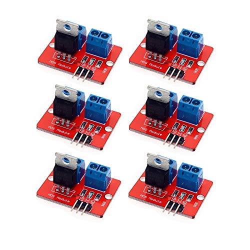
I just setup an ESP to control some PWM computer fans that are in my battery box (I live off grid and my home runs on batteries at night). You need a mosfet chip between the ESP and Fan to control it.
From the ESP connect the 3.3v, GND and a GPIO pin to the MOSFET. Connect a 12VDC power supply to the MOSFET, connect two wires from the PWM fan to the MOSFET. Below is the ESPHome code running my fans (I have two sets of fans run from one ESP)
esphome: name: battery_fans platform: ESP32 board: nodemcu-32s
# wifi settings wifi: ssid: !secret wifi_ssid password: !secret wifi_pw power_save_mode: none ap: ssid: "batteryFansAP" password: !secret ap_pw
captive_portal: logger: api: ota:
output: - platform: ledc pin: GPIO23 frequency: 10000 Hz id: battery_fan_in - platform: ledc pin: GPIO22 frequency: 10000 Hz id: battery_fan_out
fan: - platform: speed output: battery_fan_in name: "Battery Fan In" - platform: speed output: battery_fan_out name: "Battery Fan Out"
Cool - mind reporting back and detailing your set up? What optocoupler are you using? Something like this?
Hi! I sure can. The one I purchased is https://www.amazon.com/gp/product/B089KTR73W. The only things I haven't really worked out is the recording/playback function. Honestly I'm not sure I'm going to spend much more time on it though because it's not really a function I care about and I don't really know how else to go about trying to track down how to use it.
To save you some money in the future: DS18B20 don't really need anything other than a pullup resistor to operate, that module is not really necessary. You can buy them in bulk - I have a few dozen of these by now, they report the authentic hardware address, and I'm yet to have a single failure: https://www.amazon.com/gp/product/B01IVN3X6K