
What are
/r/Motors'
favorite Products & Services?
From 3.5 billion Reddit comments
The most popular Products mentioned in /r/Motors:


The most popular Services mentioned in /r/Motors:
Banggood
SlideShare
Circuit JS
SemanticScholar
Screencast.com
The most popular reviews in /r/Motors:
I don't think this is the exact solution to your problem, but it's definitely worth looking at.
https://smile.amazon.com/gp/product/B01BBSXDJ4
​
I use these **TINY** N20 motors with gearboxes for a few projects. They are the smallest and lightest solution for you for sure. They are about 25mm long (including the gearbox) and weigh almost nothing.
They are SURPRISINGLY stong, and with the gearing, they don't like to turn when they aren't powered so that would help with your "hold when stopped" request.
They can be geared for different speeds, but they do have a 300RPM option
- Perhaps you can replace the PTC relay with a current motor starting relay.
- The PTC relay probably works for 0.1-1sec so you could replace it with a manual off/on/mom switch to give the starting coil a push each time you start the motor. You could probably leave the PTC in the path for extra protection - and it will cool during operation (because it's not powered).
If you wanna use PWM for control, cheap brushed motor controllers for a small RC car (1/18-1/16th scale) on Amazon or Ebay from Chinese sellers would do you just fine
Ex: YoungRC 30A ESC Brushed Electric Speed Controller for DIY Mini RC Car or Boat Tank w/Brake https://www.amazon.com/dp/B07MX3514Y/ref=cm_sw_r_cp_apa_i_0vtfEb64VW381
The fans kill the engine when the engine is already at normal idle speed? Seems like you have other problems, but you might try something like this:
https://smile.amazon.com/gp/product/B01M4PXFBG/
I use one on my Jeep that I converted to an electric fan. I have an Arduino that controls the fan speed based on coolant temperature, and eventually I plan to factor in AC status and vehicle speed.
You could also use it to do a soft start on the fans.
Thanks for your detailed response! This is the sort of controller that I have on hand.
I then put that through a DC rectifier to create the DC. I tried it on a DC treadmill motor that I had and it works great, but like I said this motor with 8 wires is a bit more confusing. I have 2 wires coming out of my DC rectifier, which wires from the motor need to be connected to that? Or do I need a much more complicated setup to also power the field windings separately at a lower voltage?
A couple of suggestions:
- The ripple in the battery chargers may be a problem for the electronics in some fans. There is also a danger of over voltage using an unregulated lightly loaded transformer as a supply. Try testing them with a battery or a cleaner power supply, like a pullout from an old PC.
- In the future, if you don't need to control fan speed, specify 2-wire 12 VDC fans such as this one:
https://www.amazon.com/GDSTIME-80mm-25mm-Brushless-Cooling/dp/B00N1Y50QQ/
Please post a link to the 5 new PWM 4 wire fans you bought on on Amazon if you want to try to get those going., but try a clean well regulated power supply.
Oh, that's easy. You either need to order them from the Acme catalog, have Tony Stark's budget, or visit Toontown to make your cartoon fantasy a reality.
Barring that, you're going to need a complex hydraulic system instead of electrical actuators.
So long as you've got a permanent 24VAC supply available you can indeed use a relay, Signal in to coil to ground, fixed 24V to common pin, NC is your output pin.
Can get a cheapo like this, https://www.amazon.com/Uxcell-a14071800ux0297-General-Purpose-Socket/dp/B00PZXGHZY , there are quite a few different options depending on what kind of connectors / mounting you want.
Allegedly they're 0.037A, but I suspect they need at least 0.5A to get started.
https://www.ebay.co.uk/itm/333759620166 is the link to the item, you'll need to view the full description to see current etc.
Pwm is required, reversing is not.
At the moment, I'm driving them using https://www.amazon.co.uk/dp/B07ZCMZW9Q/ but that board will only do two channels, not 16, and having 8 of these boards just isn't feasible for the space I have.
The L298N can safely draw 2A max, but your motor will take about 4A right when it starts up. If you turn it on slowly (via PWM from the Arduino), that'll work perfectly fine. That being said, I always like using these beefier motor drivers for stuff like this - it's super overkill, but you won't have to worry about thermals.
Sure - so, you're going to need to be able to output some amount of torque. If you're open to some programming and wiring, you can use an Arduino, a motor + worm gearbox, and a motor driver, with a potentiometer on both the steering wheel and the rudder, with a PID controller to close the loop.
Would you see any other simple way to control voltage directly in circuit? over time I want to build a feedback circuit to keep airflow stable. the airflow sensor is connected via i2c.
So, to output 19A at 24V, you'll need (assuming 90% efficiency), 24V/(12V * 90%) * 19A = 42A on the input. I don't trust cheap modules like those much, especially when I don't know the controller IC being used - I'd guess it's going to lower the output voltage if the input current exceeds 40A.
Maybe check out something like this: https://www.amazon.com/Cllena-Converter-Voltage-Regulator-Transformer/dp/B07S185GXF
It's pricy but it'll work.
Okay, here is something like what you need: "Current sensing switch" https://www.amazon.com/Current-Sensing-Normally-Adjustable-SZC23-NO-AL-CH/dp/B07N1P6TWL
If you put just one wire from the EVSE or outlet through the sensor (red or black), then wire the motor through the K1/K2 switch contacts, it should turn on when the car starts charging. You have to adjust the current setting on the relay.
Check the current rating also. That sensor relay is only rated for 0.5 Amps. If your 12V motor draws more than that, you can switch a control signal of the motor controller. Or perhaps switch the AC side of the 12V power supply, where rhe current will be less.
It can be found on Amazon here https://www.amazon.ca/MHCOZY-SelfLock-Interlock-SmartThings-Required/dp/B08YY7XFS3/ref=dp_fod_2?pd_rd_w=P8Hxz&content-id=amzn1.sym.2e87565b-5db7-463f-b603-f0dc9a67b4c2&pf_rd_p=2e87565b-5db7-463f-b603-f0dc9a67b4c2&pf_rd_r=T71T91Q3077ZNQ...
You can research the module from there, and one of the product shots is a hookup guide.
This is basically what I want.
Do you have any idea what that motor is and what the controller would be?
This is just the first result that came up, and it seems to have all the specs. I can't speak for quality or anything. VFDs like this are usually pretty comparable in features, so I'm not sure you need to be on the lookout for anything special, as long as it's rated for single-phase input (some are not) https://www.amazon.com/Variable-Frequency-Inverter-Converter-HUANYANG/dp/B0775S7KFW
I’m thinking of opting for the AEMC 2126.53, 1000V, it’s at 270 I believe it would be sufficient for this testing, what do you think? megohm meter
Pool was working fine yesterday. Today I noticed it did not come on. I reset all the breakers. When I tried to turn it on, I hear humming, but no action. Google leads me to try the capacitor first. I cut all the power and safely removed it. I'm having trouble finding an exact replacement tho. Wanted to see if I could get some help here before I did something 'close' but potentially harmful.
Pool pump capacitor https://imgur.com/gallery/R6o6FP2
This is closest I've found so far. But volts higher. Is that ok or keep searching?
I found another one (link just keeps going to main site and imgur messing up) and all the info is the same. But the uF is only at the lower number and not the full range. Not sure if that is an issue or not.
Thanks for the suggestion. The schematic is similar to this one, but couldn't find a power source on Fritzing similar to the one I'm using. I've never used an optocoupler but will try to see if I can find one. Do you think that it could be some weird feedback issue from the power source through the PWM pin?
What is your control signal? A logic relay board may work for you? https://www.amazon.com/Xiuxin-Channel-Relay-Module-Arduino/dp/B07C8LSXKC/ref=mp_s_a_1_8?crid=7H3D6PZWD4MM&keywords=relay+board+5v+10+channel&qid=1656513683&sprefix=relay+board+5v+10+channel%2Caps%2C90&sr=8-8
Just replace the whole mechanism, they are dirt cheap.
Unfortunately, power/rpm/torque is the starting point you'll need to, well, start at ;)
For the rod to motor coupling, you can just hack together a shaft - you could probably 3D print it. If you don't have access to a 3D printer and you make the design, I'll print you it for free plus the cost of shipping - open offer.
If you get a spring scale then you can measure the force needed to tension the wrapping while rolling it, that could be used to get a torque-needed estimate.
If you're just looking for a basic "good-enough" motor and power supply, you could pick up something like this and this and see what you're looking like.
Can you elaborate on "I don't know how to stop the friction" ? I'm not understanding that.
Depending on what else you have going on in the case, a fan controller may be sufficient to drive your motors. You can power the fan controller with a sata power connector and hookup the motors to the pins on the controller. However, this means you would have to spec the motors to whatever the fan controller says. Other option is you tap power directly off a sata connector but you would lose the ability to control the “speed” of the motor. I believe more recent sata connectors include 3.3v , 5v and 12v pins. So.. you could tap off the 3.3v supply and use one of these guys https://www.amazon.com/dp/B00GYRSDSE/ref=cm_sw_r_cp_api_i_4AKMM1X9HF0CGHMY2TWK?_encoding=UTF8&psc=1 as your motor. Bottom line, its possible, just be extremely cautious. Shoot me a message and ill see what I can do to help.
It's complicated... as you can see here, but in general - yes - all the contacts of the commutator are connected together trough the windings. The resistance value should change and usually be higher on opposite contacts.
I wouldn't be able to just use an inline resistor or something to lower the speed or something else?
Maybe my grammar is poor. I want to just plug in the battery and have it go at a set speed and not fuck with it all since it's being suspended from a kite line. When I say "control" I mean I want to the speed (TBD later) to be regulated while it's doing its own thing.
Yeah I can buy one of these things but once the speed is set I'd have to hot glue the pot and hope it holds up during the journey to wherever I launch it from, plus it's all dead weight.
So yeah I am basically looking to make something from scratch, hopefully I can reuse the gutted servo board.
Not sure what your weight constraints are but they do make 1-2 rpm gear motors:
https://www.amazon.com/DC-Reducer-Motor-Worm-Gear/dp/B00NL7EW44
This one draws 0.18A @ 6V, could use a 9V battery or 1-2 18650 cells and a cheap DC-DC converter to regulate it to 6V. If you don't need speed control or wireless operation you could just mount a switch at the motor.
You're adding a resistive load to control the voltage - that's going to result in a worst case power loss of about 25W (1.6A ^2 * 10 ohm), probably blowing up your potentiometer. You can get high power potentiometers, but that's an overkill solution. Something like this should work fine - it'll "chop" up the voltage to the fan depending on how you turn the knob, which will reduce the speed.
This is water and electricity, I've no doubt in my mind that "i" can do this, but i have no idea of your abilities. Be careful.
I'm assuming the motor only has one wire for positive, and one wire for negative. Open the pump housing, find the motor, disconnect the charger, and splice in one of these:
I wouldn't use the one above myself, but it looks like it might be easier to understand than this:
If you're really interested in electronics, you could buy a power supply and some cheap dc motors to start learning. If this pump wasn't for water or give you much more detail, but once again, water and electricity
Maybe 1, .5, 0 ohms? I really don't know, it's definitely something I would experiment with.
You could pick up a cheap set of 1 ohm power resistors and experiment with different series/parallel combinations.
You can use a buck converter to get voltage down to 5-6 volts. I could not see the stall current of the motor on the page you linked, but i think https://www.banggood.com/DC-DC-CC-CV-Buck-Converter-Board-Step-Down-Power-Supply-Module-7-32V-to-0_8-28V-12A-p-1245047.html this one should work.
I dont know if power tool batteries have the BMS in the tool or battery, you should check that, if it is on the tool you can drain the battery too much and damage it.
Well, you'd have to find some specifications on the motor. Voltage and current being important - match voltage and meet or exceed current - and I haven't dealt with them much, but it seems they can have a particular number of "steps" per rotation, or resolution. I assume most drivers can be programmed, but may need to be matched at a hardware level.
After the specs the important question becomes what you'd want to do with it. CNC? There are a lot of cheap controllers with firmware for specific tasks that will already talk to PC software for operation, and many where you would have to program the controller for movement, or interface with a processor. What your goal is would tell you what direction to look.
Random example: STEPPERONLINE CNC Stepper Motor Driver 1.0-4.2A 20-50VDC 1/128 Micro-Step Resolutions for Nema 17 and 23 Stepper Motor https://www.amazon.com/dp/B06Y5VPSFN/ref=cm_sw_r_apan_glt_i_3W1VCWXAHZGCX056VGG9?_encoding=UTF8&psc=1
ya, ive just started experimenting for a project. im using a PWM controller to limit speed to about 10% of total capacity, which will draw much less current which is in range of the 420mA 12V power supply I am using. seems like it is just maximizing/overloading the power supply on current draw. as far as i understand, this motor at 12V will get like 3000 RPMs and im looking for about 300 RPMs. my experiment, at first, was full power to the motor for 3000 RPMs, which showed the same signs you are getting, which is overloading the power supply.
https://www.amazon.com/gp/product/B007TH4EN6/ref=ewc_pr_img_3?smid=A298K45OP416LP&psc=1
ill switch out the pot on this board to 10k or so (from 100k) to achieve what i want. i hope tangentially this can help someone. cheeeeeeers!!
its for a leslie/rotory speaker cabinet with speed control :)
So I got this IKEA Desk for free on facebook marketplace.
The previous owner’s house was struck by lightning, and the desk no longer will go up or down. I bought a new power supply to see if that was the problem, but it still does not work.
So now I am thinking it may be the controller. I found this one that I am considering purchasing.
I don’t have much experience with this kind of thing, so I can’t tell if the other boards are shot. Any help or advice on how to get this working again would be appreciated!!
I just tried using 6aa batteries in series so it was about 8v and it was much faster, but still not as torquey as the wall adapter at 5V. so does that mean its more of a current problem than voltage?
I found on Amazon a flashlight which includes 4 rechargeable 18650 cells and a charger, is this the type of battery you're talking about? (most lithium batteries take about a month to arrive but this kit arrives in a few days and includes the charger)
my concern would be if I used these batteries like you said i would have 7.4, but i wonder if it could still supply enough current
Have you looked commercially? Like this?
If that doesn't work, why not?
I tried the above and the device won't start
I measured the output with a voltmeter, while rotating the potentiometer, but I could not see any variation in voltage ..I am returning it, I will probably buy this https://www.amazon.ca/gp/product/B01MXQG4UZ/
Do you think this one would work?
AC Light Dimmer Module For PWM Controller 1 Channel 3.3V/5V Logic AC 50hz 60hz 220V 110V
​
And Thankyou for that explanation. I was about to return it because 1 step fan sounded like it only could have one speed.
1.) I see several problems here that could cause stuff to blow up. You’re hooking a 5v panel to a 3V battery, which could cause some issues. I would look into using a Lithium Battery Charging Board https://smile.amazon.com/dp/B06XCXPY86/ref=cm_sw_r_cp_api_glt_fabc_CC4J52F7D18401GVPS62 and a 3.7v Li-Po battery. Also, the motor would spin way too fast. You might need to make a gearing system to slow it down.
Either with a blind bearing puller or if you have a grease gun with a tip that just fits inside that inner race, insert and firmly hold that tip in place and pump grease in behind pushing the bearing out.
I'm unfamiliar with that part, the internet calls it a start switch, is it just the starting contact switch like what i posted below? (I've always called it a starting switch relay)
As far as I know, the MSL rovers use BAE RAD750 processors - they're pretty common for space missions, and they're the successor to the IBM RAD6000s that were used for Spirit and Opportunity.
The information on motor hardware seems to be a bit more difficult to find, but it looks like a purpose-made ASIC driving a set of Maxon RE25 motors.
The motor is expecting a PWM signal, which you can't generate with a pot. In some systems, PWM is just low-pass filtered to an ADC and you could just run an analog voltage to it instead - but I don't believe that's true here, because of the wide (2-5V) input voltage range specified for that signal.
You'd need to convert your potentiometer output to PWM. Something like this could work. You'd want to set it to 10-20 kHz and 5V NPN output (because the motor appears to have an internal pull-up, so you want NPN to pull down). Note that the input polarity of the PWM signal is inverted (i.e. low = on), so 0% duty cycle corresponds to 100% output and vice versa.
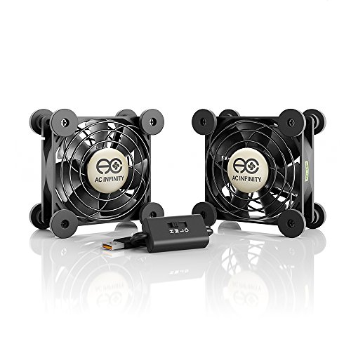
Stop trying to reinvent the wheel. You need the Airplate:
https://www.amazon.com/AC-Infinity-AIRPLATE-Thermostat-Cabinets/dp/B00QFWWZQO
Six fan speeds, automated control, virtually silent. However, if you MUST do this as a DIY project, read this:
https://www.analog.com/en/analog-dialogue/articles/how-to-control-fan-speed.html
My apologies - my knowledge is so basic, I struggle to use the right terminology.
Someone more experienced than me built a capacitor circuit by combining an integrated circuit, two capacitors in parallel and a resistor.
This is the electrical diagram, and this is how it looks like.
I want to build something similar, both because I suspect I will need it and because I wish to acquire the associated skills; my question, however, was about whether or not I can purchase a finished product with comparable functionality.
3D Printer TMC2208 Stepper Motor Driver, DORHEA TMC2208 V1.2 Stepper Driver Module with Heat Sink Screwdriver for 3D Printer Controller Mother Boards Reprap Ramps1.4 MKS Prusa i3 Ender-3 Pro, 5PCS https://www.amazon.com/dp/B082LSQWZF/ref=cm_sw_r_cp_apan_glt_fabc_2ZNYC8WYBCPQASDG13PK?_encoding=UTF8&psc=1
This is what I purchased.
I've just been plugging this into a breadboard and setting up the motor, with appropriately paired coils, as well as the power rails.
I configured the current using the potentiometer as instructed, as well.
I might just have a flawed understanding of the operation, as most guides are for different uses than mine.
Would something like this work, or is it unnecessary?
Yes it's the interior circulation fan. It's basically identical to the item from the link above. It is a DC motor
That controller is not a stepper driver, its a pulse generator to feed into a stepper driver.
You can see schematics people have posted in the amazon reviews as to how it needs to be wired: https://www.amazon.ca/DC5-12V-Adjustable-Controller-Generator-Regulator/dp/B07HNSVMVH
You're likely overloading the power supply on startup, it's gonna pull way more than 10A at zero speed. Can add a speed controller with soft start to limit the current to a sensible amount and will also let you control the no load speed, example cheapish module https://www.amazon.com/Liyeehao-Protection-Ultra-High-Control-Maximum/dp/B08CXL2S7P
You could probably run the fan on less than 12v and be fine. Crossing the 12v line momentarily should not hurt the fan either.
Maybe this:Gaiatop USB Desk Fan, Small But Powerful, Portable Quiet 3 Speeds Wind Desktop Personal Fan, Dual 360° Adjustment Mini Fan for Better Cooling, Home Office Car Outdoor (Black Blue) https://www.amazon.com/dp/B08TWLKWYV/ref=cm_sw_r_apan_glt_fabc_Z1E9RE726EDRC2Q54BY9
I found the following motor, but I believe it may be way under powered to do it. Dimensions wise, it's like perfect for the enclosure that the fried motor is in.
https://www.amazon.ca/gp/product/B00HDDXBEY/ref=ox\_sc\_act\_title\_1?smid=A1IQ6DRJX762AU&psc=1
Good excuse for me to start. Fix a $300 appliance.
Now what projects can I do with motors and my 3D printer...
I need more than just my soldering iron anyway for this so I'm looking at This kit looks good
I really want something like alligator clips but its not included and idk where mine are. Hate to buy more
Maybe? It doesn’t mention anywhere that it’s a motor speed controller though…it also can only put out 40mA.
Low Voltage Dc 1.8v 3v 5v 6v 12v 2a Motor Speed Controller PWM 2PCS https://www.amazon.com/dp/B07MK1SKRT/ref=cm_sw_r_cp_api_glt_fabc_TWATERZVK8K1HPNZV18S?_encoding=UTF8&psc=1
This is better suited to your needs.
For a device that small, and for someone with little experience I would recommend getting a stencil for your PCB so that you can apply solder paste and reflow the part. I think trying to hand solder a tiny QFN would be asking for trouble.
I just bought one of these hot plates for soldering but have not used it yet. I've heard good things though, particularly that they are more foolproof that a toaster oven or a hot air rework tool.
May I ask you: why do you want to do that? It seems like a lot of design effort for something that you're unlikely to ever need to use. And something you can buy ready-made quite inexpensively: https://www.amazon.com/American-crank-powered-flashlight-smartphone-ARCCR100R-SNG/dp/B003BYROUQ/
A few more questions then. Do you really need variable speed or just slower? Are you ok with 3 speeds, like a house fan? Do you have 230V available? And since it is in a greenhouse, do you need agricultural grade (typically moisture resistant and heavy duty)?
One option is a 3 phase motor with vfd for true variable speed (can use single phase input), but these are rather expensive
If you want a quick and cheap hack though, get an HVAC motor that can be wired for multiple speeds and use a swtich https://www.amazon.com/Fasco-D701-5-6-Inch-Enclosure-Reversible/dp/B007VJO1OE/
Drawback is these are not made for agricultural duty so it may corrode in your greenhouse.
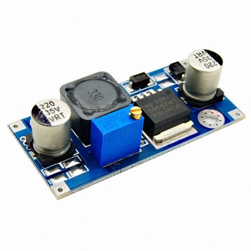
The standard way ender 3 people tend to do it is by using a buck regulator module.
Usually the lm2596 or similar like this: https://www.amazon.com/LM2596-Converter-Module-Supply-1-23V-30V/dp/B008BHBEE0
There's plenty of cheap pwm fan speed controllers that work up to 24v on eBay/Amazon etc that might be a simple way of getting what you're after. This for example was one of the first to come up.
If you want to get a bit more fancy and have the fan speed react to temperature changes it gets somewhat more complicated. You could do it with a thermistor, a 555, a MOSFET (and a couple of other bits) for example, I'm sure there's guides online. Or go the Arduino route. Or search out a 24v compatible thermostatic fan speed controller, there's plenty for pc case fans, most are 12V, but I'm sure someone's selling something that would work at 24v.
Ahh I see. You seem to know more than me so I probably can’t help you, but I did find one other cheap driver board - https://www.amazon.com/dp/B01CP18J4A/ref=cm_sw_r_cp_awdb_imm_t1_TA754V80H5G0QNKSM1BR?_encoding=UTF8&psc=1. Here’s one for a little more than like 1$ -unit. This one comes with a bunch of extra crap but you might be able to find the board itself for sale somewhere if you like this driver.
Also you could maybe buy the Texas Instruments DRV8825 chip instead of the board if you really know what you’re doing
Good luck!
For clarification: In-rush current usually refers to the current needed to charge up capacitors to their working voltage in a circuit. What you are experiencing motor stall current (At the exact moment you apply power, the rotor is not turning and is effectively stalled until the rotor gets up to speed.)
Motor stall current can be many times greater than the nominal current. According to your datasheet, the motor stall current is 21.6 amps. (this is just the motor voltage divided by the equivalent winding resistance)
What you said was the nominal current is actually the current at which the motor runs most efficiently (max mechanical power out per electrical power in. See the efficiency vs torque curve at the bottom of the datasheet)
The actual current of the motor will be somewhere between 0 and the stall current depending on the load. (look at the current vs torque curve on the datasheet)
It is quite likely that the motor is running well above 4 amps and your power supply detects over current and shuts down. You can get a current limited power supply which lets you set the maximum current. A constant current power supply (sometimes shortened to CC/CV for constant current constant voltage) automatically drops the voltage when the current exceeds the set value.
They arent even that expensive. See here.
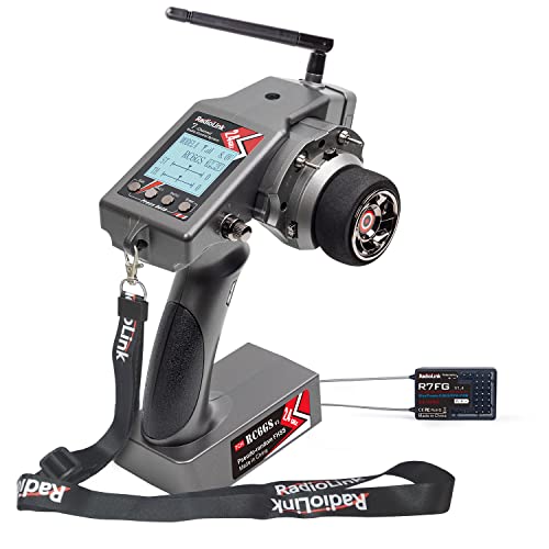
I have a 135VDC 18.8A motor for a treadmill. The controller for the treadmill died on me so I tried replacing it with a very simple controller. I wired it up in the diagram above using https://www.amazon.com/gp/product/B00MLZ1AT2/ref=ppx_yo_dt_b_asin_title_o02_s00?ie=UTF8&psc=1 as the V_reg and a full bridge rectifier. I tried it without a capacitor and the motor had a loud hum I'm assuming from the ripple of the power source so I added a 1500 microfarad capacitor in parallel to the motor. I understand a capacitor will have a good amount of inrush current so I wait a couple seconds before turning it on to get on the treadmill. But when I get on it almost immediatly blows the breaker. THe weird thing is when I took the capacitor back out and I walk on it nothing is blown. So have you any idea why adding a capacitor would pull more current?
Thank you for your help!!! Sorry I wasn't specific... I have a 12v brushed motor that's part of a big gear box to make it slower... With more research, I have realized that I need an electronic controller of some kind... Basically I want to make this geared motor into a servo and I have read that you can use a potentiometer to set up something like this: https://i.ytimg.com/vi/LXURLvga8bQ/maxresdefault.jpg
I want my "servo" to work with this controller: https://www.amazon.com/gp/product/B07DPNNTWT/ref=ppx_yo_dt_b_search_asin_title?ie=UTF8&psc=1
Can you recommend an electronic controller to accomplish this? Thank you!
Thank you for your help!!! I'm not sure what you mean by "rating" (sorry, inexperienced) but my budget is within couple hundred dollars if needed. Basically I have a 24v powered wheelchair motor and I want it work work as a drive motor using a standard RC car controller. I own this one: https://www.amazon.com/gp/product/B07DPNNTWT/ref=ppx_yo_dt_b_search_asin_title?ie=UTF8&psc=1
My treadmill blew out, and I did some poking with a multimeter to narrow it to the lower control board not sending current to the motor. I think I'm out of my depth in identifying the blow in the mothorboard (though that'd be great!) My plan is to power the motor directly from a wall plug. I'm a mechanical engineer (so I have a geeeeneral understanding of electronics). I'm using it as a walking desk so I only need 20-30 VDC input (tested speed with a multimeter). While I'd love to use something simple as a laptop charger (and then if I need to step up/down with a simple circuit that's fine), I'm worried that it couldn't handle the loads necessary (though I don't know how to test the load required!)
​
Do I need to go for a more "heavy duty" variable dc power supply like here) or is that overkill? (I don't need high precision of course...resolution of 1V is pleeenty) Or perhaps because the motor sticker says 19A, my power supply has to be ~25V + >19A?
​
Additionally, I searched around to find out what that plug is, I'm not sure if it's a standard T plug (or really if there is such a thing :) ). Can anyone identify it? Or help find where to buy plug to fit in it?
​
Lastly, I'm not sure if I need to be concerned about wire/connector loads, or if most things I will find will be able to handle the load I'm looking for.
These are probably too big but this is almost a complete solution for you
sure, this might be easier though, could cut and solder the ends to make it more compact or just leave it all plugged in.
I found a very nice adjustable power supply on Amazon I like for these occasions:
https://www.amazon.com/dp/B07HGQXW9V/ref=cm_sw_r_cp_api_glc_fabc_MYW0FbWJCF2JH
Love the voltage screen on it and versatile enough to be moved to other projects after this one it done.
Maybe a bit expensive for a “permanent” solution but easy to use.
I ordered some high temp 14AWG, 600V rated, silicone insulated wire. Supposed to be good up to 200C. I measured the existing stuff at about 0.074" so I figured it was 14AWG. This is the stuff I got: https://www.amazon.com/gp/product/B089D8M68B/ref=ppx_yo_dt_b_asin_title_o00_s01?ie=UTF8&psc=1
Does that count as lead wire? If not, where should I buy it?
I have plenty of heat shrink, and I also ordered some insulating varnish. But what kind of string should I use? Does it matter? I have some common twine if that will work.
So far all I could find was them being called "Nucleus-M Brushless Wireless Follow Focus Motor". Would this imply a brushless DC motor, or could a stepper also technically be called "brushless" since it doesn't have brushes?
Removing the speed requirement makes this much more affordable, but generally speaking, linear actuators in the 1m range will still be somewhat pricey.
Looks like something like this might be up your alley. Being belt driven, it should be pretty quiet outside of the noise of the motor itself and it is right around 1m in travel.
You'll still have to add a Nema23 motor, but those are fairly affordable all things considered ~$25ish dollars.
He shouldn't need anything close to 150A.
Nothing wrong with having them be 480V rated, that will help make them more resistant to voltage spikes that would fry a lower voltage SSR.
But 150 amps is just ridiculous.
If I were in his shoes, and I was sure I wanted to go the SSR route, I would probably pick something more like the Omron G3NA-220B-AC200-240 . (Though be aware, that is the "controlled by an AC input" type. Which might not be right for his system.)
What is your question? Start at the left: Red Black Gray for the first valve. Start at the right: Gray Black Red for the second valve.
Do you just want to run them on a manual switch?
I'm not sure how you are trying to attach the servo to a 1/4" rod, however it might be a multi piece connector depending on application, here is an amazon link to a servo that comes with 5 generic connections that you can bolt a second clamp to.
if you are going to a direct connection to spin the rod, look at this
Buy one of these motors and some nylon pulley wheels. Drive a small pulley with this and connect it with a belt to a much larger pulley. You're all set.
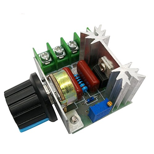
uniquegoods AC 110V 120V 220V 230V 10000W High Power SCR Motor Speed Controller Voltage Regulator Dimming Attemperation Thermoregulation Board https://www.amazon.com/dp/B01M3XZBV9/ref=cm_sw_r_cp_api_fab_YWLFFbPQGVWDV
It uses a potentiometer to fire a triac for pwm control. It’s not as effective as a VFD but it’s wayyyyy cheaper. I have one on a 120v blower and it works great
> So I guess, around 10N
https://www.amazon.com/Uxcell-a14032200ux0077-Actuator-Electromagnet-Solenoid/dp/B00KKKNVAG
Is that too big?
> servos with metal gears
I think that's the wrong approach. Instead of a servo motor (limited rotation), use a regular motor (unlimited rotation). To convert the rotary motion to alternating motion, couple it to a cam and a plunger. Or a crank mechanism (such as in a car engine). Ask in /r/MechanicalEngineering.
Get one of these, check wire without insulation.
1-Is it not running at all, or is it not running smoothly IE jerky?
2-Did you connect it back exactly the way it was?
3- Did you get the correct amount of turns?
4- Did you have the correct amount of wires in hand?
5-Did you measure how many amps it's pulling with the new winding?
6- Is the resistance correct and consistent for every lead?
Get you something like this with an arduino. You drive the board with IO pins on the arduino board and program the arduino.
Thanks!
​
Is this an exact replacement? https://www.amazon.com/Ugtell-Capacitor-Capacitance-Frequency-capacitor/dp/B075ZJ76P4/ref=psdc_306788011_t3_B075ZKT5M5
Full disclosure: I am a tinkerer, not a proper EE, know what you're doing before following my advice. I'm also dyslexic so double check all the labels and their meanings and wire colors cause I'm currently not in front of a real machine to double check anything. That said:
Maybe? My guess would be it'll work, but fail prematurely, I base this entirely on anecdotal evidence and hand waving. Motors and LEDs are very different loads (inductive vs resistive iirc) but some PSUs don't care, some do. usually the ones that don't care don't have an application in their description. That said, the link you posted is more expensive and less watts than https://www.amazon.com/MEAN-WELL-LRS-350-12-Switching-Constant/dp/B07BH1FTYP which I know can run 12v 8a rated motors (I've used them to do so, but motors aren't all alike, there's more to an electrical load than amps and volts.) Your link also has a brand name that looks like the designer fell asleep and hit their head on the keyboard, so chances are every spec is ... Embellished, and chances of you finding anyone to talk to when it decides to pursue a career in noise generation are zero.
To plug it in, cut a PC power cord, there should be a green, white, and black wire inside, black goes to L (live), white goes to N (neutral), green goes to the little downward arrow esque thing (ground). Also connect v- to ground, then V- and V+ can be connected to the load. For 8A you want reasonably thick wire (less than 20 guage, smaller guages are bigger, stranded or solid are fine, if you're going more than 5 feet, consult an ampacity table).
IP67 (intrusion protection, vs particles level 6, vs water level 7) is for weatherproofing, if you don't need that it's just going to add cost.
Tl;Dr I bet that'll work, but it technically isn't the right tool for the job and it's kinda pricey.
For example, would something like this work? Looks to meet the amperage requirement etc from what I can see:
LED Driver 250W 12V, Waterproof IP67 LED Transformer,LED Power Supply 110V AC to 12V DC Low Voltage Output with 3-Prong Plug 3.3 Feet Cable for LED Light, Computer Project, Outdoor Light https://www.amazon.com/dp/B07Y61R8SR/ref=cm_sw_r_cp_api_i_1NWoFbFA2QR54
Most dc to dc buck and boost converters have ~~constant current control. I would just check to be sure yours features that.~~ (Edit: brain fart, forgot how amperage works, mkrjoe explains it well) As for the power supply I would just get a generic one like this: https://www.amazon.com/outstanding-Supply-Adapter-100-240V-Transformer/dp/B01N1IHK2A And mod it (cut the barrel connector off and strip it) to use it with your desired voltage converter.
It's some variation of a gear reducer pancake motor. Like this maybe? https://www.amazon.com/Egg-Turner-Motor-Sports-Outdoor/dp/B07GDDDRW7/ref=pd_day0_c_60_3/130-1838532-0029319?_encoding=UTF8&pd_rd_i=B07GDDDRW7&pd_rd_r=33a6a0bd-cf9e-4fbe-b4c6-e085d7683671&pd_rd_w=GoTAR&pd_rd_wg=qWkYr&pf_rd_p=52c...
Thanks! That's very helpful. So If wanted to power a small motor like this: https://www.amazon.com/gp/product/B00PNEQI7W , I'd get an Arduino like this https://www.amazon.com/ARDUINO-MEGA-2560-REV3-A000067/dp/B0046AMGW0 ... but I'm not sure about the relay or h-bridge step. Could you link to an example of one? Thanks again.
Ok, thanks. So I'd buy a controller like this: https://www.pololu.com/product/3131
Then a stepper motor like this: https://www.amazon.com/Stepper-Motor-Bipolar-64oz-Printer/dp/B00PNEQI7W
Is that right? I'm totally ignorant of this stuff.
The telescope needs to rotate at different speeds (between 0.5 and 1 degree per second) depending on the angle and on the time of the year. Therefore, you need a servo control (that includes a variable speed motor) that is smart enough to know the above.
Synchronous motors are anything but variable speed, so, no, that's the wrong motor for your application.
My strong recommendation is to buy a kit to convert your telescope to a sky-stationary one, such as this one.
I'll try to post the link again, if it still doesnt work you can find it by typing in "Car door lock actuator" in amazon, it should be the 4 pack that has the label "amazons choice" on it for heavy duty car door lock actuators. Sorry!
TL;DR: probably not great for the gearboxes of the motors, definitely not good for the raspberry pi or motor controller on the logic side. Use a buck converter.
Long Answer: Ah, the classic yellow gearbox motors. I've got fond memories of using those things to make a line following robot in uni.
To answer your question, I'd advise against it for longevity reasons. AA batteries have I believe about 1.5v typically, so you'd be running a 6v rated motor on effectively 9v (at least until the batteries lose some charge). While the brushed DC motors in that gearbox could probably handle that voltage, the gearbox might not be able to take the subsequent boost in RPM and power for too long. We're not talking catastrophic failure here or anything, more likely you'll just strip out the pinion gear in the gearbox pretty quickly. For reference I'm calling the pinion gear the small gear attached directly to the motor that you see if you decide to take apart the gearbox.
Those motor drivers can only take about 5 volts on the logic line (VCC), which I believe is all a raspberry pi can take too. These you most definitely will fry at the voltage that 6AA will send down the line.
My reccomendation? Regulate the voltage from the batteries using a buck converter like this one which can be found at Amazon here. This particular DC to DC voltage converter is somewhat expensive at $11usd for 2, but it is good because the screw terminals mean it requires no soldering, it displays the output voltage for you, and it can be reused for a multitude of projects in which you need a regulated voltage.
Just my two cents, but I really which someone had told me about the importance of good voltage regulation when I was starting out.
Feel free to ask more info. PM me if you like, but I like having discussions out in the open for anyone who stumbles across threads later
would this be fine for the power supply?
LE Power Adapter, UL Listed, 3A, 120V AC to 12V DC Transformer, 36W Power Supply, US Plug Power Converter for LED Strip Light and More https://www.amazon.com/dp/B00DKSI0S8/ref=cm_sw_r_cp_api_i_6muwEbZNZA5PM
i don’t know how to connect it, i just found it on amazon.