
What are
/r/beneater's
favorite Products & Services?
From 3.5 billion Reddit comments
The most popular Products mentioned in /r/beneater:


The most popular Services mentioned in /r/beneater:
Digital
Hackster
Autodesk Tinkercad
FileFactory
Vim
gow
Gofile.io
Circuit JS
Logisim
BOOLR
iCircuit
GIMP
Inkscape
Snipboard
HackMD
The most popular reviews in /r/beneater:
Adding to that, I would highly recommend getting a decent digital scope, an LCR meter, e.g. like this one, and becoming familiar with some kind of circuit simulator software (LTSpice, circuitlab.com etc.). Three things that make debugging wonky circuits a lot easier.
Sure. Vim is a keyboard-based text editor included with most OS’es if my memory serves me right. [Vim Website] To open vim from the terminal or bash window or whatever your OS calls it, type “vi [filename.extension]”. That will open up that file in Vim, or create it. Navigating vim is confusing at the start so I’d suggest looking for a YouTube tutorial on how to use it.
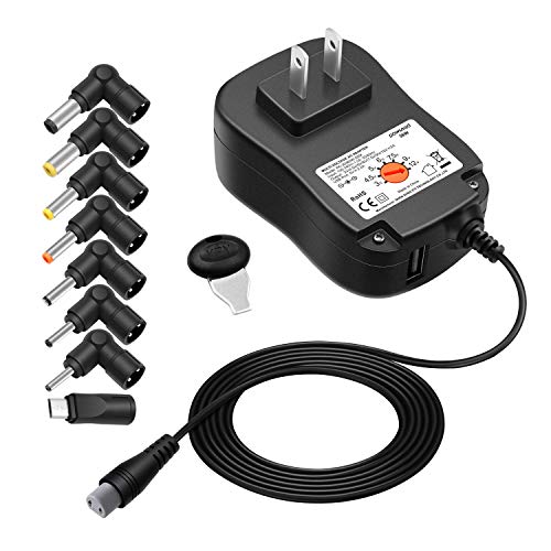
It’s just a temporary thing because I had it nearby. I’m probably going to switch to one of these for power once I feel like finding out where I put them. I do find being able to use a 9v battery pretty convenient though.
Logisim is fine, but quite old and is not actively developed anymore. And there are only "generic" parts - e.g. NAND gates, but you can not get 74x00 chip.
Edit: /u/gfoot360 was talking about Logisim Evolution, which is a continuation of original one.
I would suggest Digital instead. It has a lib with 7400-series DIP chips - correct pinout, multiple units per chip. You even have to connect VCC and GND pins.
Flex PCB connectors such as that, typically connect to a PFC or FFC socket.
The data sheet on the LCD will be required reading, and it should tell you the pin count plus the actual pin spacing.
Purely by eye I would guess 40 pin and 0.5mm spacing. Thus a "FFC40/0.5MM" connector.
Amusingly the first search result wasn't for the connector, but for this adaptor board: https://www.amazon.com/uxcell-Converter-Couple-Extend-Adapter/dp/B07RT6YCP4
Once you look up the pin count definitively, I'd personally look for the proper adaptor board like above, because SMT soldering the connector itself is going to be a PITA
For now, I want to build a breakout type game using sprites. To control it, I want to use a potentiometer and an analog to digital converter. Eventually I’d love to build this into a full computer with a DIY keyboard. I find this project very inspiring for its form factor and built in keyboard.
Direct amazon links (not referrals):
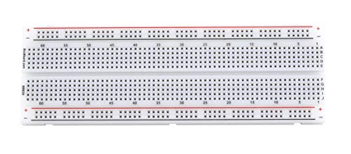
https://www.amazon.com/BB1660-Solderless-Plug-BreadBoard-tie-points/dp/B00MOLIUUU/
https://www.amazon.com/BB630-Solderless-Plug-BreadBoard-tie-Points/dp/B07GY1WMV1/
If you buy them, make sure you get the ones that are sold by Busboard themselves, look for:
"Ships from Amazon
Sold by BusBoard Prototype Systems"
I got this soldering iron kit last summer and it working well enough, I'm still really bad at soldering though, I need to practice more, here is a link to a logic analyzer that Ben eater links on his website on one of the 8 bit computer pages
In terms of the 6502 upgrades, I'd recommend for sure doing the 6551 serial upgrade early on, it's pretty helpful
I'm there with you brother on pixel-y color patterns... endlessly fascinating to me too. Have you found https://processing.org/ yet... you'll love how it expands what you can do on the screen to large and small display devices.
Check this site out. https://www.hackster.io/david-hansel/breadboard-computer-programmer-1e7a09 It worked perfect for me.
I agree, particularly with the first paragraph.
Ben's CPU videos coupled with Harris and Harris https://www.amazon.co.uk/Digital-Design-Computer-Architecture-Harris/dp/0123944244 is a great way to get junior EEs started with FPGAs.
I would start from there (CPU), but you won't be missing or struggling with anything if you start from somewhere else, or jump around a bit.
Those posts cover most of it, but I'll repeat one item mentioned in those posts. Buy a good pair of wire strippers. It will make this project immensely more enjoyable. I'm using these.
You have two options buy second hand, but sometimes you see that people just ask overrated prices for 20 year old oscilloscopes and secondly how would you know as beginner that the device is 100% correct.
New, something like this https://www.amazon.nl/Hantek-DSO5102P-2-kanaals-oscilloscoop-real-time/dp/B00I5EWF1U/ref=asc_df_B00I5EWF1U/?tag=nlshogostdde-21&linkCode=df0&hvadid=430611520751&hvpos=&hvnetw=g&hvrand=1974504288048126091&hvpone=&hvptwo=&hvqmt=&hvdev=c&hvdvcmdl=&hvlocint=&hvlocphy=1010718&hvtargid=pla-492226249648&psc=1 is fine. If after a while you get fed up with electronics you can always sell it. Or the Siglent 1202X-E, very good scope. But not cheap. scopes just are expensive
Not answering your question, but I highly recommend getting a cheap oscilloscope if you can afford it.
I got a 2 channel device on amazon for $150. They have single channel ones for under $50. The reviews will tell you how terrible they are, and compared to “real” bench oscilloscopes I am sure they are terrible. But the difference between having a crappy one, and not having one at all is huge. I learned a lot from using it to help build, test, and debug my 8-bit CPU.
First thing I know nothing about color blindness. I assume you see shades of gray. So I was wondering if you could use this and match the shades to the resistor?
I was using an arduino 5v output for a while, until I bought this power supply: https://www.amazon.com/gp/product/B071RNT1CD/ref=ppx_yo_dt_b_asin_title_o07_s01?ie=UTF8&psc=1
I would be very interested in seeing more of your PPU, it's something that I'm thinking about building myself and I'm keen to learn more!
Ben Eater's videos on generating a VGA signal are really helpful, and I can see the appeal of a character based video output.
I found this book on the ZX Spectrum's hardware that has a very nice explanation of how its' simplified character based video output works:
https://www.amazon.co.uk/ZX-Spectrum-Ula-Microcomputer-Computer/dp/0956507107
I'm using this 24awg at the moment and it's OK but still rather thick insulation: https://www.amazon.co.uk/gp/aw/d/B07V3C686H?psc=1&ref=ppx_pop_mob_b_asin_title
The dispensing box is handy for sure.
Before that I used this, which has thinner insulation and worked really well for me: https://www.amazon.co.uk/Velleman-MOWM-Assorted-Full-Core-Mounting/dp/B001IRVDV4/ref=mp_s_a_1_5
It's a really nice thickness and quality of wire. I didn't pay that crazy delivery cost though, not sure what's going on there.
Another option you might consider if you're on a budget, I bought one of these:
https://www.amazon.co.uk/gp/product/B07K14NR8P/ref=ppx_yo_dt_b_search_asin_title?ie=UTF8&th=1
(VGA to HDMI adaptor) and it works fine with my beneater inspired GPU
If your looking for the 28C256 I think you can just find them on Amazon. Thats where I got mine from. Here is the one that I got
Quickly looking at the picture, the first thing that comes to mind is to get a 0.1uF and 0.01uF cap on the VCC of each IC (as others have mentioned). I would have a 10uF cap on each power rail, too. Assuming that you're plugging your power supply into the top rail, measure the voltage at the far bottom and post what it's at.
I have experimented with different breadboards, and the BB830 boards have been consistently the best. I have had significant power distribution issues with non-BB830 boards, similar to what you're using.
Are you missing the D0 connection on your EEPROM?
Ty.
I used these hook probes to hold the resistor and the LED leg tightly together.
I've added .1uF capacitors to the power rails around the NAND IC and to Vcc+GND of the NAND IC. I've also switched from using the first NAND Gate to using the second (A2 B2 Y2) gate. Now this seems to kind-of work.
I do not get any unintentional memory writes, but still, I see these voltage drops in the output line:
Channel 0: Buffered clock input
Channel 1: Rising edge after .1uF capacitor/resistor
Channel 2: Output of NAND (Y2 this time)
Channel 3: Supply voltage close to the NAND IC (this seems to be quite stable)
So I still observe this drop - which appears to be mitigated a little bit. But I still do think that something is wrong?
Cool! Right shift is a very useful thing.
For those of us stuck with just the adders: remember that you can left shift the A register by copying it to the B register and writing the ALU sum output back into A: https://hackmd.io/81jIB5OtQ1G4Ru35ne5EkQ
Hello! Great status videos, keep them coming! ;-) Good way to get feedback
I had the exact same issue with these switches. Even if I got the right pin pitch, finding switches with the right pin length was hard. Switch kept popping out of the breadboard. I settled for a solution that a lot of people do, which is to solder the switch to header pins like these. You can see my handy work here. So yeah, a bit of learning if you haven't soldered before, but worth it. Not only useful for securing the switch to the breadboard, but also to create very stable connection points for the power supply to the breadboard!
I will never not upvote someone embarking on this incredible project. Good luck, take your time and spend extra time measuring your wire cuts. And if it fits your budget, I cannot recommend highly enough a good pair of wire strippers.
ARCELI TL866II Plus USB High Performance EEPROM Flash BIOS Programmer for ATMEL AVR ATMEGA AT90 PIC GAL SRAM CMOS https://www.amazon.com/dp/B07CQQBGVK/ref=cm_sw_r_awdo_JMQ3NBBB6QA2PE6HPFNB
Def worth it for me to get, it’s just so helpful and works with many different chips.
Many come to wisdom, some start at hardware, reading upon semiconductors, diodes, transistors, proceed to logic gates and on (love Charles Petzold book "Code" that goes in that direction).
But some start from hello and sporadically gain other bits (if ever).
Many Java devs I've interviewed over the years have no idea what 0x100-1 will be and don't care.
Here’s one thats still good for me amazon
u/OkFlamingo, I had a similar idea and bought a 19" Ottoman tray from Amazon: https://www.amazon.com/Whitewashed-Serving-Handles-Removable-Chalkboard/dp/B07578D782/ref=sr_1_6?keywords=19%2Bottoman%2Btray&qid=1649710062&sprefix=19%22%2Bott%2Caps%2C131&sr=8-6&th=1 (when I bought it, it was somehow a lot cheaper than $30...) and placed a 19x19 plexiglass cover over it, which I got at a hardware store.
Ya', I thought I would either pull out an old ATX case or order an open-frame ATX case. Something like this or this. I was considering adding support for an ATX power supply (e.g., ATX power connectors on the motherboard), but I decided to hold on that for now. One step at a time. Plus, I know I'll need to spin a revision of these boards as I learn from my mistakes.
u/bigger-hammer has done some ISA work, so it's definitely possible to use 3rd party cards. I don't plan to put energy into that right now, though. I'll use the ISA physical infrastructure, but not the official protocol. I want to get '816+VGA+Sound, with keyboard and mouse, working. I then want to learn more about emulators (I've done zero in this area so far) and continue some game development.
Search for "mdfly zif breakout"
I bought the 40 pin 300-600 mil (0.3-0.6 inch) one for $10 on amazon, which isn't all that much more than just a ZIF socket alone (these things are surprisingly expensive!)
It has both screw terminals and female pin headers which works with standard breadboard hookup wire. Makes it nice and flexible to re-wire for different chips (the c16 is a bit different than the c64 and c256)
So, what difference does the 100MHz and 50MHz have?
Is this the correct one for the 100MHz? It's cheaper but looks like it has less features. Some reviews said stay away from the older model. I don't know what model this is.
If the 100MHz is better, I would get that because it's cheaper anyway.
Honestly know nothing about these, but I'm going to buy one anyway so I can learn about them.
u/EnchRDL; BTW - I also had purchased this off Amazon for my power adaptor to breadboard, for my 8-bit breadboard computer project. I use the female adaptor piece.
FYI - They have different amounts you can purchase...8 bought this one because it came with both female + male.
Hope this helps. Good luck!
You have eagle-eyes! I got those from Amazon. As for power supply issues, join the club... we all have them at one point or another. lol
mxuteuk 120 Pcs 0.1uF 104 100nF Multilayer Monolithic Ceramic Capacitor 5.08mm 0.1uf-104
https://www.amazon.com/dp/B08B3VCK42?ref=ppx\_pop\_dt\_b\_product\_details&th=1
I've been testing my logic designs for the 6502 computer in https://github.com/hneemann/Digital which has a bunch of 74xx logic defined already. I'm not sure if it'll take you all the way to the 8-bit build since some of the more esoteric 74ls chips may be missing, but you can build that stuff out of gates.
I know it's an old post, but still, in case anyone else finds this i want to recommend something:
The powerful logic simualtor called Digital has the ability to export Logic Circuits to a WinCUPL comaptible format, meaning you can just open the generated .PLD file in WinCUPL and compile it. it also allows you to directly compile from the Logic Simulator if you point it to where WinCUPL has it's files located (in the settings).
Digital also allows you to export Circuits as Verilog or VHDL, which is useful for FPGAs or larger CPLDs like the AFT15xx series (which btw is supported by the free version of Quartus II under the MAX7000 devices, which are perfectly compatible with the ATF15xx devices).
overall the Logic Simulator is amazing if you want to test your logic designs before throwing them onto a real chip, or if you're just better/faster at building logic circuits than writing them. so far i've pretty much never had a difference between how the logic simulator and the real hardware behaved
Depends on what you mean. If you want to draw a schematic that can be used to create a PCB then Kicad would be the way to go.
If you want to be able to test how a digital circuit will work, then Digital - which is used for Fpga design - is a great way to test circuits before you build them: https://github.com/hneemann/Digital
You might wanna grab "Digital" https://github.com/hneemann/Digital and use it to build your logic schematics, since it has most of the 74* logic chips already in it & you can double check your work by simulating the circuit. It really helped me sanity check.
As a bonus it can construct a truth table and then make a JED(?) file from the truth table you can burn to a GAL for your custom logic. Haven't used this feature yet though, so IDK.
I don't know if I paid for it or not (I do a lot of stupid crap when I'm drinking), but I was looking through my Kindle library this week while I'm on vacation, and I saw a "Programming the 65816" e-book. I read it (I'd already read 3 novels this week - geesh, I should have brought my Arty-7 to the beach and worked on VGA maybe?), and while it's not the absolute best technical reference I've ever read, it was... surprisingly informative.
Free on Kindle Unlimited, if you have that (my wife reads about 3 books/week every week, so it's worth it to me). It's worth a read, even if it doesn't make you a bona-fide Apple IIgs or SNES programmer.
well, i got these breadboards (10 for 20 bucks) which I consider quite cheap and quite decent / high quality
MCIGICM 10pcs Breadboard 830 Point Solderless Prototype PCB Board Kit Protoboard MB-102 for Arduino DIY Electronics kit https://www.amazon.com/dp/B07H9X7XVN/ref=cm_sw_r_apan_glt_fabc_Y1WTCDAK07VTSB0YAVJK?_encoding=UTF8&psc=1
well, i got these breadboards (10 for 20 bucks) which I consider quite cheap
MCIGICM 10pcs Breadboard 830 Point Solderless Prototype PCB Board Kit Protoboard MB-102 for Arduino DIY Electronics kit https://www.amazon.com/dp/B07H9X7XVN/ref=cm_sw_r_apan_glt_fabc_Y1WTCDAK07VTSB0YAVJK?_encoding=UTF8&psc=1
I got mine from Amazon - here's an example:
https://www.amazon.com/Aceirmc-TL866II-Universal-MiniPro-Programmer/dp/B082D5NQ2P/ref=sr_1_3?crid=1BIK7P7LRQQJM&keywords=minipro&qid=1640966161&sprefix=minipro+%2Caps%2C260&sr=8-3
TL866II is the real name. It'll program damn near everything (I think even Atmel/Microchip microcontrollers). Instructions and manufacturer support seems weak, but instructions exist (in English even) that got me and many others through it.
I suspect that's a short rather than a broken connection on the power rails. If the power connection were breaking then I'd expect to see just part of the board go dark instead of the whole thing.
I wired the power feed through a cheap ammeter on my build to catch the kind of large draws that you get when a chip is installed backwards or when two outputs are both driving the bus at the same time. I caught several wiring mistakes with that.
the rom legs are so flimsy. buy this https://www.amazon.com/Glarks-Breakaway-Connectors-Arduino-Prototype/dp/B01GY36RJY/ref=sr_1_38?crid=27A4L358O3P8L&keywords=2.54mm+female+header&qid=1639872569&sprefix=2.54mm+female+header%2Caps%2C88&sr=8-38 and check out the row of headers in the first picture on the far left. You can stick the legs directly into those and it makes it really solid and easy to put into a breadboard and programmer without bending anything.
A review on https://www.hackster.io/news/65f02-is-a-100-mhz-drop-in-replacement-for-vintage-8-bit-computers-ef667b0ebed3 this 65F02 would be interesting ...
I recently bought this item:
https://www.amazon.com/dp/B077SFGWYP?th=1
I wanted a breadboard power supply. This one also supplied a bunch of jumpers like Ben uses. After having them, there's no way I'd go back to using a breadboard without them.
Highly recommended!
Yeah, reddit markup is a mess. If it looks good for you, then I think the problem is with old reddit, so I wouldn't worry about it.
In any case, here's how your post looks for me: screenshot.
The only change I had to make for it to work on old reddit is to add ### to the start of the list titles ("Order by xxx", etc.) and add an empty line before the first item, like this:
### By Logic type/family:
* CMOS - ABT/(... etc ...)
But since it works on new reddit and no one else complained, I don't know if it's worth the effort to change it.
Try taking a look at these:
For TinkerCad, you'll have to create an account. Once logged in, click on "Circuits" button on the left.
I was in your situation when I started this project. I have a software background and basic understanding of circuitry.
I second /u/overpowering_ligma in that the clock module is probably the hardest part since it's the first one, and includes a chip, resistors, capacitors, and leds; everything you will encounter later. Once you get past this module, the rest follows the same logic and it becomes the most fun thing to do and more Lego-like.
I used the circuitry section of TinkerCad to get me started with understanding things better and while it's not the best tool, it's very easy to use and has everything you need to (virtually) build the clock module or even your own version of it.
I originally experimented with this in iCircuit, but when the Reset pin is held low, the Discharge pin is connected to ground. At least in the simulation, this caused a bit of weird behavior and significant vampire draw.
It's tough to work around because discharge, threshold, and trigger are all connected to one-another. When reset is held low, you want discharge to be connected to ground (to avoid current draw) but the trigger must be held high (to avoid an invalid internal state). I didn't come up with any ideas on how to fix this other than cutting power to the chip entirely but I'm all ears if you have a way to fix it!
Also it's entirely possible that the issue I saw in iCircuit was just an artifact of the simulation. Looking at the diagram, as long as Discharge is connected to a voltage source through a resistor (which it is), the current draw should be somewhat limited.
Oh yeah... almost forgot... if you like Logisim, you'll love Digital:
https://github.com/hneemann/Digital
I find it much more intuitive that Logisim... personal opinion...
I've been using https://github.com/hneemann/Digital which is a spiritual successor to Logisim; I don't know how it compares feature-wise to logisim-evolution but it's been quite easy to set up.
It also has the cool feature of being able to generate JEDEC files for programming 22V10 GALs.
This is my first project using Digital, so if more experienced users have feedback, I'd love to hear it.
Similarly, if you spot any bugs in what I've built so far, or are interested in contributing, I welcome that as well!
/u/weirdboyjim, if you see this, let me know if you have any objections to this and I'm happy to take it down. Otherwise, if you want me to include any different text/licensing information on there, let me know.
Assuming this continues, the ultimate result should land on a full simulator of the build that can run at a few KHz, and it even supports attaching an IDE/build process to push bytecode to it for simulation of real programs.
I've exported a couple of the modules as verilog as well, and adjusted their testbenches to work with the IceStorm toolchain, and run it through the verilog simulator--so far the results align to the results of the tests.
When I get far enough to have the CPU functioning, I'll throw it on an actual FPGA and see if it works.
I've mostly used https://github.com/hneemann/Digital to simulate circuits, and it works pretty well. It's also actively maintained. The interface is very similar to logisim, but I found it more reliable for complicated circuits, and I really like the ability to put test cases directly into the circuit.
I've made a video of the attempt to use Xmodem. It simply hangs when I select the file to send. Nothing shows up on the terminal screen.... Am I doing something wrong ?
http://www.filefactory.com/file/zac2uz2qwt4/KrisOs_1.mp4
( ignore the beep at end of video. my phone got a txt while recording !)
I will try the other options you suggest .
Thanks Dawid.
Thanks
I like the idea about the gutter numbers being in hex rather than decimal. It should also probably start at zero instead of one.
Also will admit, the "0x0" arguments after HLT & OUT are not intuitive. This was simply done to keep the Parser Engine's logic as-simple-as-possible. But I agree, it should not be necessary.
The Control Word Labeling is a little trickery because we are limited by screen-real-estate. I have some ideas on a compromise. If you hovered over the Sequencer Box and a popover/tool-tip appear with the control word abbreviations ( LA, EA, SU, LR, ER, EA, etc...) would that be an improvement. It might look something like these examples: Bootstrap Tooltips
Also if you want to track these issues, feel free to submit requests on our GitHub.
This will allow you to get updates about progress in the SDLC. Use this link: New Issue
If you don't care to track them, I will probably add them sometime next week.
PS
Did you use the 8Bit Tutorial on the Docs Page. If so, it would be great to get your feedback on those.
Thank you. Added an on board Arduino to Save and Load programs primarily. We can even edit and modify programs with this, using the serial connection. Special thanks to David Hansel for his very useful post at: https://www.hackster.io/david-hansel/breadboard-computer-programmer-1e7a09 He used a UNO but I did it with Nano using the same sketch. The computer will start automatically once you set the DIP switches to the position where the program is stored. You may set the DIP switches to Zero for putting in new programs, then select the number at which you want to save the program, press the save button. Thats it!
The idea is not mine: https://www.hackster.io/david-hansel/breadboard-computer-programmer-1e7a09
From above I only build the RAM programming part, toggling in programs with DIP switches gets old very fast. I had to modify the software however, since I don't have 16 bytes but instead 32K RAM. So addressing over several RAM pages was a must.
So I used the idea but built my own software.
The same principle I used for the interrupt controller, it uses the CE line from the EEPROM's and control of the computer is taken over by an MCU a 16F877A. This time however it was my own idea, own implementation and software, not stolen from somewhere else. (big smiley)
Then in the Arduino IDE:
First all instructiona are defined: # define MVI_A 0b00000100 etc etc etc
Then in the setup part I define an array with the instructions, like
/*000*/ MVI_A, 0, 250, // load accumulator with 250
/*003*/ SUB_B, 0, 0, // subtract content B register from A register
/*006*/ MVI_CA, 0, 0, // move content A register to the C register
and so on
I have to track were each instruction goes, that's the reason for the numbering.
It looks a lot like programming an EEPROM, only now it's RAM. The Arduino does not know the difference.
Yes, it was the WiFi that caught my eye (plus there's an app for that, and who doesn't want to program their <$200 8 bit computer with >$1000 phone?)
The other project I've been looking at prior:
https://www.hackster.io/david-hansel/breadboard-computer-programmer-1e7a09
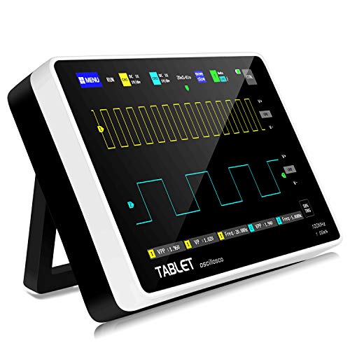
If you have the money, I say go for it. I bought one and it definitely helped me.
I got this one for just under $150:
YEAPOOK ADS1013D Handheld Digital Tablet oscilloscope
It’s definitely not great, but it helped a lot with diagnosing some errors, and it’s relatively cheap. Others have advised against it, recommending more expensive ones, or kits that work with computers.
Also these, might have to solder header pins to it if you're still using bread board, but they are nice and small:
https://www.amazon.com/WS2812-Channel-Color-Driven-Development-Arduino/dp/B081BBF4R3/
For testing I would get something like this RS232 to TTL (https://www.amazon.com/dp/B074BTGLJN/ref=cm\_sw\_em\_r\_mt\_dp\_4HEWDD5E2PJVQKRTVZN8) . It uses something similar to the MAX3314E chip which converts 5v to the +/-12v RS232 uses. If I was going to do this I would use the RS232/TTL board connected to an arduino to figure out the output from the serial mouse and then migrate to the 6551 once I understood the output from the mouse. I've used the RS232 to the 6551 for my system to use an old computer with a serial port to act as a terminal.
https://www.amazon.ca/BusBoard-Prototype-Systems-BB830-Solderless/dp/B0040Z4QN8/
Make sure the seller is BusBoard Prototype Systems when you buy off Amazon CA.
Does Jameco ship to Canada? They stock them, too.
I've used these before: Amazon Link
There's 4 channels per board, and that is a 10 pack for $7 USD, which will give you 40 level shifted signals total.
I can't tell if they come with the pin heads soldered in, but with them it would even breadboard friendly, or as friendly as it gets
I received two new AT28C256s from Amazon and we are back in business. I tried soldering nwew pins on and it didn't work so well and other pins were also weaked.
I also ordered some flat sided Spudger Tools which make it much safer to rextract the rom ship from the board. Highly recommended!!
Yeah!
So I’ve copied Ben eaters circuit exactly, with one difference. The difference is I added one 74hc32n, which is a quad OR package. I use all of this chips gates to produce a 2.2us delay. It delays the register clock 2.2us from the shift clock.
My keyboard is connected exactly as Ben’s is. I probed all of the 5 PS/2 wires coming out of the keyboard to see what they are and am using them accordingly.
I just recently looked at my Amazon order, and I don’t think these chips are made by TI like I thought. Maybe you can spot if these are garbage?
Glarks 40Pcs 74LSxxx and 74HCxxx... https://www.amazon.com/dp/B08L3GZGRB?ref=ppx_pop_mob_ap_share
Is there an easy way I can share a scope and breadboard picture with you?
I'm gonna give this a try.
https://www.amazon.com/gp/product/B00IWSHEB0/ref=ppx_yo_dt_b_asin_title_o00_s00?ie=UTF8&psc=1
I don't think it's the exact same stuff ben uses but https://www.amazon.com/Elenco-Hook-Up-Colors-dispenser-WK-106/dp/B008L3QJAS/ref=sr_1_2?crid=3ET0ZYH42L71H&dchild=1&keywords=elenco+hook+up+wire&qid=1609718166&sprefix=elenco+hook%2Caps%2C211&sr=8-2 worked well for me.
Cheap bench supplies cost much less than the Ben Eater boards.
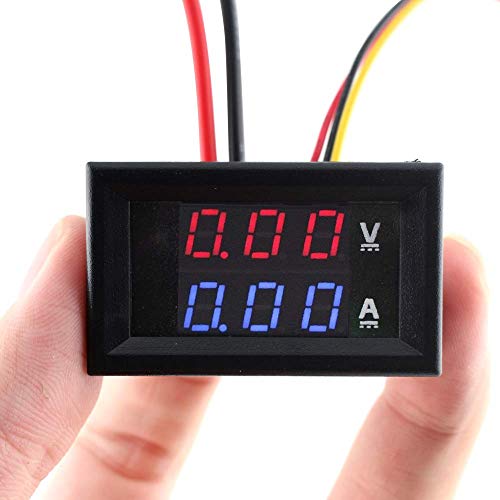
If you don’t have the funds for an adjustable power supply, look into one of the cheap digital ammeter modules on Amazon. I have one like this wired into my power supply and it has quickly shown me the high current draw the few times I shorted something or connected two outputs together. Not sure how accurate it is, but for less than ten bucks and will certainly show when there is a problem. It’s also been cool to see the current slowly increase as more modules have been added to the build.
https://www.amazon.com/Eiechip0-28-Digital-display-Volt-Meter/dp/B079L33VG2
/u/hetremis ATX supplies 3.3v, 5v, 12v, -5v, and usually -12v
Usually more than one "rail" for each voltage, each rail having its own amperage limit. Even the lowest end crappy 200W PSU will give 10+ amps on the 5v side.
ATX supplies make excellent bench-top power supplys when you don't need truely variable voltages or adjustable current limiting.
There are even cheap pre-made breakout boards with proper fuses, banana jacks, and switch to control the supply.
The primary advantage is the dangerous high voltage stuff is kept inside where you don't need to muck with it, you use the existing low voltage wiring just like computer building enthusiasts have done safely for decades.
Although I should add that presumption is based off a working PSU not needing repaired...
There is an “Arduino Host Shield” on Amazon (for arduino uno r3 and arduino nano). It’s literally a breakout of the MAX chip with the required 12 mghz crystal oscillator for the chip and some resistors on board. I used the nano shield, which requires logic level converters to communicate with the computer (since the chip is 3.3V). The Uno r3 shield has logic converters on board. Oh and the 6502 can still run at 1 or 2 megahertz (or more), the chip itself though does need a 12 mghz oscillator (which the shield has).
Those particular ones are Chanzon brand 2x3x4mm "square rectangle" LEDs
https://www.amazon.com/gp/product/B01C3ZZT1E/
That link is the reds, but they have green, yellow, and blue too. Both clear and colored lenses. ~$6 usd for a pack of 100.
DigiKey has a few others, but tend to be more expensive and most are 3x3x5mm. In their LED section filter on Mounting type = Through Hole , Lens style = Rectangle
Since breadboard holes are spaced 2.54mm apart, I wanted the width less than that so tried the Chanzon brand, and so far have been very happy with them
This is amazing! Thank you for being such a cool significant other! We need more people like you. In response to your question this kit looks amazing for him and with it get him a Logic Probe (https://www.amazon.com/Elenco-Electronics-LP-560-Logic-Probe/dp/B000Z9HAP4/ref=sr_1_5?dchild=1&keywords=Logic+Probe&qid=1608368724&sr=8-5) as this well be a tremendous help learning about hardware! Good luck!
Thanks for the reply! So I’m not the only one impressed with the wiring I’ll look into those wire cutters I currently have a T&B WT2000 And Heres my current project so I can get some feedback if anyone wants to currently I’m designing a casing for it so I’ll see how that goes. And I’ll definitely look at those wires you gave me I want to not have pure white circuits lol
So there are two ways beyond what has been mentioned that can be used to get that super sharp look. First is a lead bender that you can easily 3d print. This is the one that I use for my leads if I'm using them in a presentation. I also use these for their intended purpose of bending component leads uniformly if appearance matters.
Additionally, I usually have a box of these assorted prebent leads ( **Amazon but not an affiliate link) around for quick layouts. For the most part, both of these items are luxury/convenience items for day to day work but when you need to make a good impression and clearly communicate the design of a circuit on a board, they're worth having around. Good luck!
The one that comes in kit #1 is Jameco part# 2227209 (you connect wires to it yourself from those included in the jumper wire pack)
The one Ben had in his video he made himself. If you want that you'd need to cut up your own USB cable and solder something to it to connect to the breadboard. I'd highly suggest only going that route if you have a bunch of unused USB cables laying around already, and a multimeter to verify the power/ground wires (the colors can lie)
Or you can get a similar USB-A to screw terminal adaptor such as this one.
Just don't plug it into a computer to get power. Use a phone charger or something that can provide 2 amps (A PC can only guarantee 0.5 amp, and will be a very expensive power supply to replace if you accidentally short circuit something)
I found for the yellow LEDs the 220 ohm was fine, ive seen mixed things online for other colors, but 1k is probably good enough. but otherwise yea exactly like that. make sure the resistors you get have thick leads too. the first pack I bought has the thinnest leads and they bend so easily. I ended up buying another pack here that is much thicker. (you end up saving by buying a pack of a bunch of resistors rather than one specific value)
To give you a little insight as to one of the things they do in China with components, check out “The Hardware Hacker: Adventures in Making and Breaking Hardware” https://www.amazon.com/dp/159327758X/ref=cm_sw_em_r_mt_dp_oIUjFb2A6PW8G by Andrew “bunnie” Huang. He’s the designer of the Chumby, sort of a “counter-top” internet “appliance” (news, web, email, etc on one device — before smartphones). I was amazed at how eye-opening the book was. There’s an entire chapter on identifying bogus, altered or counterfeit parts; for example, USB thumb drives that are larger than originally marketed — i.e. turning an 8GB thumb drive into a 32GB. They do this by activating the “spare” sectors of the chip normally reserved for “bad blocks” (i.e. when a part of the memory goes bad, the thumb drive remaps “sectors” to the spare sectors. Another thing they like to do is dumpster dive for parts that are no longer used or ones that don’t pass QA from the manufacturer and resell them. Tell-tale sing of shady hardware — if it shows up in a Ziploc sandwich bag, it’s probably got issued :).
I picked up a resistor kit, from Amazon, that has 134 different values, with 25 pieces per value 3350 pieces in total). They're 1% tolerance, 1/4 watt, metal film resistors - 5-band marking's. It came in a clear, plastic container/case, with each value in an individual, little zip-lock baggie. For $25, IMO, I find it to be worth the buy!
If the link below didn't work or show up, you can search for the following (copied from the title of the item in Amazon): "Cutequeen 134 Values 1% 3350 pcs RoHS Compliant Resistor Kit x 25pcs =3350 pcs (0 Ohm - 4.7M Ohm) 1/4W Metal Film Resistors Assortment"
Link is as follows: https://www.amazon.com/gp/product/B017L9GKGK/ref=ppx_yo_dt_b_asin_image_o02_s00?ie=UTF8&psc=1
Hope this helps!
Frustration avoidance is worth at least $5.
Can you tell me what are the properties of a 'shitty' solder, I don't think I have sufficient knowledge to identify one. What are the pitfalls of using such a cheap soldering rod?
following your advice, I searched for the hakko product, is this the one(https://www.amazon.com/Hakko-FX888D-23BY-Digital-Soldering-Station/dp/B00ANZRT4M/ref=sr_1_2?dchild=1&keywords=hakko+888&qid=1585677819&sr=8-2)?
You said, but different kind of solder heads, i am unsure where the point head is used versus where the chisel head is used. Can you help there?
Also I believe you said there are other thig like solder and flux and heads I need, sponge as well? Alcohol to clean after? Can you help me identify links in amazon which are compatible with the hakko solder? Given that I am really new, actual links help. I apologize to have to ask you this.
For a frame of reference, lets say, I want to practice building a radio, before I try to build the ben eater kit. Lets say I will build this kit(https://www.amazon.com/Elenco-FM-88K-FM-Radio-Kit/dp/B004YHZE0G/ref=sr_1_2?dchild=1&keywords=eleco+radio+kit&qid=1585689758&sr=8-2-spell). I am using actual examples, because I have a feeling the head needed to solder will depend on how dense the PCB is?
I picked up one of these on Amazon:
https://sigrok.org/wiki/Lcsoft_Mini_Board
Super cheap, 16 channels and works with Sigrok were my criteria. Very happy with it.
Specifically this one:
I used almost half the room on 3 solderless breadboards making a bus with 24 .3 inch connections and 48 .8 inch. Then got frustrated with making neat connections over to it in the available space and wired everything with rainbow arches of wire going over to the CPU, RAM, EEPROM, VIA and my address decoder.Shockingly, it worked - even at 1 Mhz.
Then in a bid for neatness and because I thought it would look cool - I used solder protoboards (Amazon) with rows of header stacking the boards in a stair-step. 72 0.3 inch jumpers. I wired over to the chips with painstakingly neat, properly dressed wires. It does look cool. But it doesn't work reliably. In fact it has really weird behaviors - like taking 20 seconds after reset and LCD inti to display Hello World on the LCD - where the very same code worked instantly on the breadboard.
Pictures (The solderless board has no ICs on it because I moved them to the new boards)
I had drawn the design up in EasyEDA already. So I went ahead and ordered the board from JLC. It hasn't arrived yet but I've gotten my shipping notice.
They are usually called "square led", even though they are rectangle.
I use Chanzon brand "square 2x3x4" which sells through amazon
( https://www.amazon.com/Rectangle-Transparent-Lighting-Electronics-Components/dp/B01C3ZZT1E/ )
SunLED is another manufacturer of brand "Ice Cube", which are on digikey, but 3mm wide which I've found doesn't fit as well on a breadboard.
On Jameco you can search on "LED Rectangular". There are a number of 2x5mm results from "lite-on.
I have no experience with the ones on Jameco, although have had great experiences with other lite-on LED products in the past.
Try jameco part# 320291 and go from there
I was just noticing yours in your image gallery. Do you have a link to where I could purchase one like that?
​
Edit: Found it on amazon: https://www.amazon.com/gp/product/B0018ZHTWS/ref=ppx_yo_dt_b_asin_title_o00_s00?ie=UTF8&psc=1
The photos on this Amazon product page show a BB830, and this was the product page I ordered from. Fraud? :(
https://www.amazon.ca/dp/B0040Z4QN8/ref=sr_1_1?m=A2RKGEIGG4B1JT