
What is Reddit's opinion of
Altium Designer?
From 3.5 billion Reddit comments
18 reviews of this app found across Reddit:
You mean the $3000/seat price + subscription? That's for starters.
And if you really want feature comparison and are too lazy to google, you can find the list here: http://www.altium.com/altium-designer/features
Right of the bat, Kicad has none of the features on the first page alone.
Kicad isn't even playing in the same league. That doesn't mean it is useless - it can actually do very good job if you use it for what it has been intended for.
However, by comparing it with Altium you are attempting to compare a bullet train with a bicycle. Both are means of transport but that's about all they have in common. If you wanted a meaningful comparison with Altium Designer, you would need to look at e.g. Mentor Graphics products or Cadence.
It's a No-ERC marker, placed by designer to have Altium ignore some rule(s) about that node, such as connectivity type. Yes, Altium will manage types of signals, like input/output, open collector, etc., and will generate errors if they don't match. If the part has pins set to passive then those are generally allowed to be connected to anything. There's a connectivity matrix in Project options that defines how types of nodes can be connected and what warning, error, etc. that's generated. http://www.altium.com/documentation/15.1/display/ADES/Sch_Obj-NoERC((No+ERC))_AD
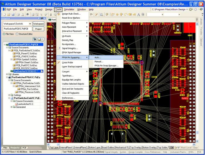
I think It's Altium Designer.
Edit: Here is a screenshot, not some of the buttons on the left.
Edit Edit: If you're looking for a free alternative, I've used PCB Artist before.
We have student licenses for $120 per year! We need proof of student status first, but we definitely support the student community.
Here's the link to our free trial page. Just select "I am a student" in the drop down and we'll get you taken care of!
You want to have the traces that lead to the smd pads oriented directly away or toward the component for a better design. Look at this.
Eagle free, limit max board size, high irritation factor
Kicad, seems to be well respected, a bit buggy
Recent Altium might very good http://www.googleadservices.com/pagead/aclk?sa=L&ai=CdWY6oND1VerUJ-qEjAbLkpnYCICXjqsH6K--u8cCgIHRiVAIAxABIMHC2BcoA2DVhYCAuAigAYD0_MYDyAEBqgQkT9BSt9vKGnr1ebO5ZPcTHG2T0T6pTGJtDtGeTAVml64TL7WVgAWQTogGAYAH6IuDOZAHA6gHpr4b2AcB&ohost=www.google....
Usually via sizes are chosen for their signal characteristics (inductance, power handling, etc) as well layout density comes into consideration as well when using different drill sizes.
That said, if you have no hard requirements on the via hole size you have a few options.
As the easiest option, design the PCB as you would for production with a PCB fabrication house. When fabricating the boards yourself, once you create the technical toolpath you should be able to override the required drills with the ones you have available. Using the largest drill you have in the tool magazine which is less than the hole diameter as an override.
Another method is to design normally for production PCB fabrication and then create a variant where you use the "PCB" window to query/select matching all vias and then the "PCB Inspector" dialog to manually change all matched vias to the size you'd like to use.
The 3rd option is to change the default via size in the PCB Editor section in preferences.
The 4th and 5th options vary depending on your routing style, if you route vias interactively or manually. If you route them interactively, you can edit via sizes in the "Favorite Interactive Via Sizes" dialog, which is also found in the PCB Editor preferences. If you route them manually, you may use the "Choose Via Sizes" dialog, which you'll find more info in the online documentation: http://www.altium.com/documentation/17.0/display/ADES/PCB_Dlg-FavoriteInteractiveViaSizesForm((Choose+Via+Sizes))_AD
Eagle is a good place to start. If you get proficient with that moving to something like orcad would be pretty intuitive.
There will be another one available in the near future. Altium has revived the circuit maker nameplate and that is hitting open beta next month. It looks like a stripped down version of altium that will be free to hobbyists.
http://www.altium.com/circuitmaker/overview
I use altium professionally and am looking forward to this one.
I've recently switched from Eagle to Altium. The benefits of Eagle are that it is fast, pretty easy to use, and cheap. There are a myriad of scripts available to implement extra features, but even with these extra options, it lacks the power and integration of Altium.
Altium is really easy to use once you get used to the weird controls (there are lots of keyboard shortcuts that make things very easy). It has just about any feature you could imagine, and integrates everything together very nicely. It also has a 3D aspect where you can add step models to the components in your library renders your board in 3D, making it easy to check clearances. The downside is that Altium can be a bit slow to do some tasks like rendering and saving boards, and I've had it crash on me a few times (I don't think I've every had Eale crash on me).
Overall, I would recommend Altium because in the end, I think the integration of features makes it a much more valuable tool. There's also a solid works interface add-on that might be useful for the ME's.
Yes. If your software supports the concept of jumpers (like this, you can treat all the segments of the chopped up physical net as one continuous net in the schematic. You then have to have the two pads of the jumper touch the net at the same place.
Given the choice between asthetics and function, I would choose function.
That said, you could probably make a gnarly looking polygon to mask out the problem areas. Another way might be to play around with the polygon 'Remove islands less than' and 'Remove necks when copper width less than' settings. Yet another thing to try is to increase your clearance settings and repour the polygon to see if it helps.
The Altium documentation says the hatched polygon settings can be modified by changing the 'Track Width' and 'Grid Size" settings of a polygon made from tracks and arcs, but I have not tried this.
You have the right idea -- what you do is to create locally defined items in the BOM catalog tab -- (http://www.altium.com/documentation/17.1/display/ADES/((ActiveBOM))_AD#!ActiveBOM-LocalPartCatalog), creating entries for your enclosure and for the manufacturing step for the enclosure modifications.
Then you add the catalog entry into the BOM components tab so that it becomes a part of the BOM.
Then in your output job, you generate the output BOM with the BOMdoc as the source file.
Just use "place holder" for the enclosure, and "process" for the machining.
Altium CircuitMaker is free, and has pretty much all the same features as the licensed version. Only problem is that the component libraries are all community driven, which shouldn't be an issue for OP if he's just using RLC discrete components.
Typically you need an Altium Live login to connect with a license, check under "DXP>MyAccount" to see if you're signed in. These same credentials should allow access to the vault - try the steps on this page - http://www.altium.com/documentation/17.1/display/ADES/((The+Altium+Content+Vault))_AD
Altium do have a free edition, it's fairly new. http://www.altium.com/circuitmaker/overview I haven't used it myself, I use the full blown version but it might be worth checking if it can edit the Altium files provided.
I'll have a look this evening to see if it's possible/practical to open the Altium project and save as Eagle.
Thank you! Eagle was used to design the circuit and Solidworks for the model.
I'm told that altium supposedly does all that automatically - schematic, to layout, to 3D model. From their promo video, this appears to be the case.
Ah well, I had more fun modeling it than I did designing the circuit. :) Plus I already knew how to use eagle. (roughly)
Altium tutorial/introduction written by my school's lab support: http://www.add.ece.ufl.edu/4924/docs/pcb/Altium_Tutorial_R2.pdf
Altium references: http://www.altium.com/community/trainingcenter/en/training-manuals.cfm