
What are
/r/microcontrollers'
favorite Products & Services?
From 3.5 billion Reddit comments
The most popular Products mentioned in /r/microcontrollers:


The most popular Services mentioned in /r/microcontrollers:
HackADay
Hackster
Snipboard
codepad
PlatformIO
Google Drive
Wireshark
Altium Designer
XCALC
Banggood
GNU Compiler Collection
Homebrew
Rust
RealTerm
Linux From Scratch
The most popular Android Apps mentioned in /r/microcontrollers:

The most popular reviews in /r/microcontrollers:
It's a No-ERC marker, placed by designer to have Altium ignore some rule(s) about that node, such as connectivity type. Yes, Altium will manage types of signals, like input/output, open collector, etc., and will generate errors if they don't match. If the part has pins set to passive then those are generally allowed to be connected to anything. There's a connectivity matrix in Project options that defines how types of nodes can be connected and what warning, error, etc. that's generated. http://www.altium.com/documentation/15.1/display/ADES/Sch_Obj-NoERC((No+ERC))_AD
Use an Arduino Mega (or e.g. compatible). It has a lot of I/O pins for your screens, lights, and buttons, and is very well supported by the Arduino IDE and community.
Buttons are wires with optional holes in them, so are compatible with every microcontroller on the planet.
You need to be more specific about what kind of LED screen you are planning on using. Are you thinking about seven-segment displays? 0.96" monochrome OLED? Or 4K HDMI?
I've always wanted to do something like this! I always found the Parallax Propeller to be a very interesting chip. It is an 8 core 80MHz (~20MIPS) 32 bit chip with built in video hardware. Usually multiple smaller ICs/controllers are used for the various areas such as video generation, interrupt handling, etc. With the propeller you just assign a core to a specific task. The native language is spin which is a bit of an odd and very unique language. The assembly language is absolutely beautiful. And the C compiler that is available is pretty good too, it's just a tad bloated.
here's someone who did something very similar and there's also a huge manual on game programming principle on the propeller. Very detailed and a lot of useful info on it! The hardware setup for the propeller is also very simple. A few 3.3V pins, a few ground pins and then connecting an external 5MHz clock. There is also an internal clock but more speed is more better. Let me know if you have any questions! :) if youre looking for a different solution just let me know. The Z80 is one of my favorite processors and will give you an awesome 70s-80s vibe! Keep us posted on where you go with it.
I agree on the ESP8266, but for this kind of project, you don't really need another microcontroller, the ESP8266 is a programmable microcontrontroller itself , even your ESPlux doesn't seem that has another processor..
Arduino is so bad.
- The IDE - but that's manageable with https://platformio.org/
- The libraries that all wanna use the same timer and have no resource management.
- The language. Polluting global namespace with global functions instead of using C++ namespaces and can't mock it for unit testing.
What do you use right now? Only a smartphone or tablet? If it's Android I see an app that you can use with the Arduino IDE: https://play.google.com/store/apps/details?id=name.antonsmirnov.android.arduinodroid2&hl=en
But long term you really ought to get a PC, doesn't matter whether it is Linux/Mac/Windows.
A line follower can get pretty complicated depending on the speeds you want to achieve, but if you're not really interested in making it fast, I have a couple suggestions you could add to it if you haven't already:
Use quadrature encoders on the motors to determine the actual speed at which the robot is going. If the microcontroller doesn't have dedicated quadrature encoder inputs, implementing this should prove to be a decent challenge.
Add a HC-05 Bluetooth module to communicate with your phone by using the uC's USART. This way, you can add an interface to change PID values on the go for the line tracking controller without having to connect to a computer.
Not only this, but you could actually send the speed data acquired by the encoders to your phone using the Bluetooth module and display it on a graph using this app.
I have personally implemented these things in a professional line follower and are quite useful for streamlining the PID tuning process. By themselves they sound easy, but once you get everything going the code can become pretty complex.
Edit: a word
Nodes in the /dev directory are created:
- as part of the boot process
- by the kernel
- dynamically by udev (Linux's device manager) as devices are plugged into the system
Linux detects and installs drivers for hardware automatically (unless the hardware is unsupported).
Linux has gotten to be so easy to use that I haven't had to mess around "under the hood" in many years, so I am not sure what the mechanism is currently that handles hardware detection.
At least for desktop/server systems all of the hardware is automatically configured during the installation of the OS (for all of the distros I have used). If new hardware is added after the OS is installed, it is typically configured when the PC is turned back on.
I have very little experience with Linux on embedded systems from playing around with the Raspberry Pi and the Orange Pi. But it has been my experience that for embedded systems setting up the hardware is handle by distro, such as Rasbian, that is installed.
A good resource for learning more about how Linux works is Linux From Scratch.
Homebrew is the most popular open-source package manager for mac os. Think about it as the App Store for open-source software. brew cask install is a terminal command to install a software package (java in our case). To install homebrew, follow the instructions here
SunFounder IIC I2C TWI 1602 Serial LCD Module Display for Arduino R3 Mega 2560 16x2 https://www.amazon.com/dp/B019K5X53O/ref=cm_sw_r_cp_api_glt_fabc_RT12B0DY1Z3FNBH00VZY?psc=1
Looks like this has a PCB that changes the parallel to serial communication.
Wow. I used the '877A for my senior project in undergrad, something like fifteen years ago. It sounds like you're using up parts on hand (good for you), but if not, the 16F1887 and 16F887 are newer replacements. (Onboard clock, more GPIOs, etc.)
The 44-pin ones are QFN; socket to breadboard adapters look like they're rare and expensive, but if you don't mind some SMT soldering, breakout boards are available:
https://www.amazon.com/Schmartboard-SchmartBoard-0-5mm-adapter-Breadboard/dp/B00K0N82ZW
Something like:
https://www.amazon.com/ELEGOO-Tracking-Ultrasonic-Intelligent-Educational/dp/B07KPZ8RSZ
$80, but the page shows a 15% off coupon which makes it a better deal than the smaller robot on the same page. The instructions are pretty good, and ELEGOO tech support is, in my experience, very responsive if there are problems.
Update: Scoping the output, I see that one byte is actually being clocked out on the pins. Apparently write collision is occurring, but I don't understand how when I am checking for byte reception complete before moving the data.
So, I found some sample code that had an explicit check for failure of the MSSP to accept a byte, and then it cleared the write collision bit and tried transmission again.
This seems to work, and transmitted data looks right, but I don't think it is correct that the chip indicates a write collision. Could this be an unidentified errata?
Thanks a lot! I'm also a bit against replicas but I was able to find this, which seems to be a legitimate version from ST
No you can program a chip before it's mounted on a board if you want. That's usually done with an SPI programmer.
Many Arduino can function as an SPI programmer simply by loading a program for it. Connect the programmer SPI pins to the programmee SPI pins and off you go.
One neat thing about Arduino is that usually the first 1k of program space has a bootloader. That's just enough code to talk to a serial/usb port, recieve a program, and store it to the rest of flash memory. That way you don't need an external programmer at all.
If you get an Arduino UNO you'll be all set to start climbing that learning curve, which is relatively modest in this case.
https://www.amazon.com/SunFounder-Board-Arduino-ATMEGA328P-ATMEGA16U2/dp/B08353DL5P/ref=sr_1_5
This is another case of the wheel has long since been invented. Nobody is getting rich off the idea. There are dozens of variations on programmable buttons in just one Amazon search. I've even seen some of these at the local dollar store.
You might make some money if you can find a niche and market to that.
Honestly, it looks a lot like a standard Arduino kit to me.
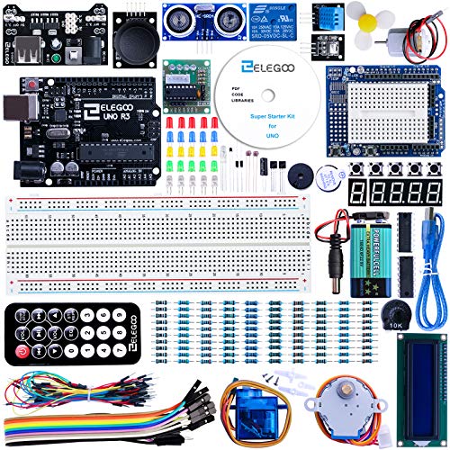
This is the one I started out with . It's got everything that nerdkit does and more, except the wire strippers and multimeter, and those are cheap enough to get elsewhere. It also has a wider assortment of parts.
So...here's the thing. You need to distinguish between microcontrollers and microprocessors.
And I say this because the applications these thing target are quite different.
Microcontrollers are...weak. They are designed to be cheap, have 'batteries included' (peripherals, memory, internal clock etc) and will be found...pretty much anywhere. They are also designed to be highly efficient...so that you can run them off of batteries.
Microprocessors are big energy consumers, with a broader application as a target. They are more powerful, have external memory (a lot, which is why it isn't included on the chip), external storage, and are able to do a lot of calculations and also in parallel.
Also...next...microcontrollers do not have an operating system (usually. we're not talking RTOes here anyway), while microprocessors have that...linux, windows, macos, bsd etc. So you're writing baremetal for microcontrollers.
Now...let's talk about your application: you want to do video processing (consumes memory and processing power) and also do live streaming (that again uses memory and processing power). So you need a lot of processing power and memory. What does that lead us to think about? Well...microprocessors. You have more than 1 core, you have ram memory, fast storage....ideal for video processing.
Also microcontrollers typically use C/C++ or Rust as the programming language. Very few use Python.
My opinion? Spend the 40$-50$ for the Raspberry Pi or the Beaglebone Black or something else that is within the range. You will spend less time figuring out things in the long run and save on development time and headaches. And...you can write ineffective code to, and improve upon it later on.
Best option for video processing, and that has ethernet? Jetson 2GB: https://www.amazon.com/dp/B08J157LHH
Sadly...it isn't available at the moment anywhere, as far as I can tell :(
I don't have a pyboard but assuming that you are using pyboard d which has BLE.
Give a try to these :
Library : https://docs.micropython.org/en/latest/library/bluetooth.html
App : https://play.google.com/store/apps/details?id=com.punchthrough.lightblueexplorer
Meaning "legit" RS-232, with negative & positive voltages reaching 15V in magnitude -- as opposed to a TTL-UART with 0V/5V logic levels -- which is to say, any cheap CP210x-based adapters aren't going to work without extra hardware :)
Is there a manual available (or a part number that I can search to get a manual)? What (PC) program did you have to use to download the code, or was the (E)PROM programming a separate step?
I'd love to take it if there are no other serious offers at the ready :)
So, you need more storage.
Got it.
You could use an SD card and store as much as you like.
How fast do you need to update the 768 byte display ??
I currently update an 128 x 160 x 3 display from an SD card at 30 frames per second using an Arduino Nano.
https://www.amazon.com/WINGONEER-128x160-Display-ST7735S-Replace/dp/B07QGCWJMV/ref=sr\_1\_18
So this one for example? SP-Cow ESP8266 ESP-12 ESP-12F NodeMCU WiFi Development Board with CH340G Lua, ESP-12F 4MB Byte Module for Arduino (2pcs) https://www.amazon.de/dp/B093G72SHN/ref=cm_sw_r_cp_api_glc_i_6CAFX78JWS6V5C1QQBJM
the 2040 does have internal pull up but every doc I've read indicates that it is pulled hi by the ps/2 keyboard and has to be asserted low only if you send a command.
what happens if I pull it up via the 2040 AND it's being pulled up by the keyboard as well??
Could this have anything to do with the voltage leveler I am using??
You don't need electronics, just some Instant Cold Packs. These are only $1 per cold packet and would be way more reliable.
This avoids needless electronics and the energy waste it would be to power such a thing 24/7 for an unpredictable event.
Being just chemical, these don't need to be charged and can be used in the middle of nowhere.
Most medical supply places should have these in stock.
They're right - bit setting, clearing, toggling is such a big deal that I had to make a whole class of instructions to do that when I wrote a virtual machine for PIC18.
It was necessary for the purpose of maintaining their atomic operation - otherwise doing a bit mask would require reading a memory/peripheral register, modifying it, and writing it back (2 or 3 virtual instructions), and in the meantime something else could modify it and screw everything up, especially when dealing with I/O pins.
Side note, if there's any interest in the ICL interpreter code & assembly macros, I could release those. The project I wanted to release them with isn't getting finished, but the actual interpreter is in good shape. The assembly macros work but are not very fun to use in picasm because there is no line number reporting possible for errors.
The useful attributes for this interpreter are: Execute from RAM or flash (or with alteration, external memory), constant execution time (68 cycles), memory write protection on 256 byte page size, multiple threads, 16 bit operations (including stack).
The ESP32 has ethernet, that may be worth looking into. Some STM32 chips support ethernet, but may end up more expensive than adding a wiznet w5500 module to a cheap microcontroller.
http://hackaday.com/2017/04/18/enabling-ethernet-on-the-esp32/
I forget whether the w5500 includes the PHY or not, the ESP32 route could end up expensive.
The STM32 portfolio is huge so I would say it is definitely worth learning.
I forgot about the extra number. I rewrote the conditions again, it works for two drawings. I tried to do same thing for three drawings, I wrote 27 where I should, but for the third drawing it shows me crazy. I'll try again in the end.
https://snipboard.io/8MOm1Y.jpg
I will also approach the application with scrolling text on several matrices, I have to make the transition from 8x8 to 5x7, because I only have one 8x8 in my drawer, and four 5x7.
Download xcalc. You easily switch between dec, hex, and binary. I've been working with microcontrollers a long time, and I use xcalc all the time to double check myself.
Also, I didn't know anyone actually used assembly on cortex m4s. I figured they'd teach assembly on an 8051 or something, then go high level for the m4.
I don't at the minute currently on a flight to Japan :D equations are simple so a calculator would be little more than simple arithmetic.
I've always wanted to do a interactive calc and will make onr when I return. Also I'd like to to give you resistors and capacitance for a given output!
They are simple rc circuit calculations if memory service t1= ln2 * (r1+r2)c and t2=ln2*R1*C. Read up about rc circuits and (dis)charging times for why this is the 555 is a very simple brilliant design in this topology. Period = t1+t2 and frequency=1/ period , duty cycle = t1/period *100 %
It will also explain why t1 > t2 in this topology (although you can do some very tricky current sources to confuse it)
(Note if you're not able to get a particular output from 555 you can always use a clock divider (counter)to make a multiple of it. 4017 (decade one hot counter) are popular pairings and with some lateral thinking you can make some interesting divisions) for example using a period of 60s with the 6 output feeding to the 4017 reset pin, or period of 30s with 2 consecutive pins driving the MOSFET and again a pin down the line resetting
edit had a layover in frankfurt (here's some code) http://codepad.org/CxvcR4n4
That's a great idea, and no polling doesn't work. http://codepad.org/u93mpZQg This code checks to see if interrupts work when I manually set INTCON, INTF (which is does) so the RB0 interrupt is working. But INTF isn't being set by the pin being changed!
I can't really think why this might be the case!
Edit: Got it! FlyVyPC nailed it, ADC needed to be turned off for PORTB. http://codepad.org/qVhITNnO
Great work.
I do a lot of embedded work and I've written a few of these apps over the last 30 years or so. The holy grail is to hex-dump 2 serial channels for TX and RX data, separating them out by time of arrival and applying custom filters to decode packet data. Something like wireshark. The difficult bit is getting accurate timestamps from your PC that represent time-of-arrival of data at the serial port. Over the years, I've tried several times to get Windows to do it and failed so now I use a dev. board with an ARM on it and upload the data to the PC where it can be decoded and displayed without worrying about timestamps, similar to what logic analysers or hardware protocol analysers do.
I have found this:
https://www.hackster.io/139994/plug-any-usb-device-on-an-esp8266-e0ca8a
esp8266 has wifi, according to this article you can connect usb device to it, and switching relay should be fairly easy job to do using few simple elements.
I learned to use STM32 microcontrollers in my college classes. My professor wrote a book about ARM Cortex M that I found helpful. He also has a website with some sample lab and info here that might help if you choose this route.
His lab info is based around the STM32L476xx instead of the STMF series.
For the more general electronics stuff r/electronics and r/diyelectronics are good resources. Book wise, you can't go far wrong with a copy of "The Art of Electronics" (Amazon UK link) for the general electronics knowledge. AoE also does contain some info on the HD44780 LCDs.
As for the microcontroller part, what resources to look at really depends on what micro you're using. Is the mention of Arduino above a stipulation or just a suggestion? If you're comfortable with C++, then you shouldn't have any issues on the software side. That is once you have a basic familiarity with the function set/ libs. The Arduino language reference can be found here. I cant't personally be of much help. Although I've used Arduino for playing about with, most of my experience is with PIC micros, with a bit of 8051.
I would say a current meter on each heater would be much more accurate, with no calculations required.
As a bonus you can turn them on and off remotely too.
Yeah, then a leo stick would be your best choice, it should work for that. Actually a Digispark DIY might work for that as well, not sure. For sure if the digispark will work it will look cleaner.
EDIT: I think I found the perfect thing https://www.amazon.com/Aideepen-Keyboard-Atmega32U4-AU-Development-Expansion/dp/B078KDW7W1/ref=pd_sbs_147_1/134-6232364-0900863?_encoding=UTF8&pd_rd_i=B078KDW7W1&pd_rd_r=4c7aee47-04fc-49b6-875e-038c3bf111f9&pd_rd_w=Blqm3&pd_rd_wg=u... IT is called the beetle and should fit your needs.
EDIT again, you can also just buy the 5pin to usb as well https://www.tinkerboy.xyz/product/tinkerboy-ibm-terminal-keyboard240-degree-5-pin-din-to-usb-converter-with-soarers-converter-firmware/ PRetty much is exactly what you are looking to do, looks like they even use the same Atmega
I found this 10 pack of light sensors on Amazon: https://www.amazon.com/Gowoops-Digital-Intensity-Detection-Photosensitive/dp/B01N1FKS4L/ref=sr_1_3?keywords=arduino+light+sensor&qid=1565710705&s=gateway&sr=8-3
Let's say I got these and attached them to each LED on the speaker splitter. Would I be able to attach 8 of them (mute LED and 7 zone LEDs) to the same microcontroller?
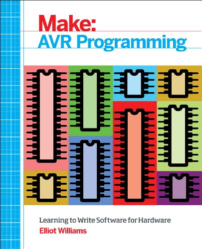
the 328p is a great chip to start out with... a lot of tutorials and guides out there. Also they have very good data sheets on everything. I suggest this book if you want a good place to start
>Pi with Wifi and a
​
My original plan included an existing ESP8266 for Internet so I won't need that any longer. Any reason for the Zero over the 3 B+?
​
I purchased both but would love to have someone else's opinion on the right solution here.
​
>12v-capable relay HAT
​
I haven't ever heard of a relay HAT so I'll have to google it. I bought a bunch of these for the relay: https://www.amazon.com/gp/product/B00ZR3B252/ref=ppx_yo_dt_b_asin_title_o05_s02?ie=UTF8&psc=1
​
>plus a cheap USB power-bank
​
I planned on using AC power (w/ a DC converter) to supply power to the relay and I assumed if I used a power supply module or something like that I could just grab 5v off that to power the Arduino and then the usb client would get it's power from the MCU.
​
I've never messed with the Raspberry products so I'll probably have to re-investigate power options. One problem at a time I suppose - thank you for your advice.