
What are
/r/AskElectronics'
favorite Products & Services?
From 3.5 billion Reddit comments
The most popular Products mentioned in /r/AskElectronics:


The most popular Services mentioned in /r/AskElectronics:
Circuit JS
HackADay
DealExtreme
Banggood
Aliexpress
CircuitLab
Alibaba.com
Hackster
Instructables
Raspberry Pi
Ngspice
Google Sites
Autodesk Tinkercad
Autodesk Circuits
Fritzing
The most popular Android Apps mentioned in /r/AskElectronics:

ElectroDroid

Color Blind Pal

EveryCircuit

AudioTool

Elixir 2

Ampere

ArduinoDroid - Arduino IDE

Expensify - Expense Reports

Share GPS
Silent Presentation Timer

Flow Free

spacedesk (remote display)

Barcode Scanner

Open Camera
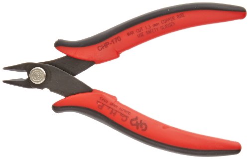
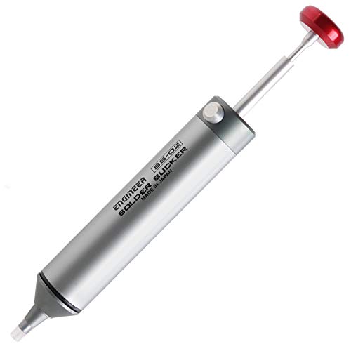
The most popular reviews in /r/AskElectronics:
Here is a direct link to a paper from 20 years ago where the author did some tests to see if right angles made a significant difference.
https://tinyurl.com/ybhzjuq2 (pdf download)
tl;dr: nope.
Why not just toss a $6 wind-up timer in each boat?
Cheap. Easy. Reliable. No learning curve. No batteries to charge. No bugs. No radio range limitations. Hard to not notice it going off. It just works.
Example:
https://www.amazon.com/MARATHON-TI030001WH-Minute-Mechanical-Wind-Up/dp/B01NAUNQ6W
I have a tough time seeing that the XY button is pushed in.
If it isn't, there is a pretty high possibility (maybe 70%) that your problem is just oxidized (tarnished) switch contacts. VERY common for equipment of this vintage. Oxidation can be in this XY button, or on the horizontal time scale switch, or somewhere else.
A nice diagnostic trick is to actuate each of these maybe 50-100 times back and forth to "wipe" the oxidation away and make it work. To play it safe, do this with the power OFF. (You can do this trick with volume controls too, BTW).
A long term solution is to pop the covers off and spray with DeoxIT. It's a bit pricey at $20, but it will it will last you a long time and is the best.
Can you let us know what you found?
Meanwell model HLG-150H-54A
54V at 2.8Amp (current supply higher than your brick, would need AC wiring... $69 Cdn
the first Amazon image is incorrect model...
its also the same price at Digikey Canada with an actual datasheet
I've implemented many full featured USB type-C ports on my devices. If you're doing the full featured specification with all the goodies, there are some gotchas - it's a complicated collection of specs, and currently many professionals still make some mistakes here and there.
The great news is that the USB consortium put a lot of thought into making implementing a "classic" USB port (with just 5V low current power and LS/FS/HS data), super simple.
All you need is a single pulldown resistor on each CC pin. You can deal with the cable flippability by shorting the two D+ pins together, and doing the same with the D- pins. The power rules are identical to type-A ports.
USB Power Delivey is a bit more complicated as it's an actual protocol with it's own unique signalling, and the power consumption is negotiated. Depending on what you're using PD for, this can make it easy or hard to use.
You can implement the PD protocol in a few different ways. If you have unique requirements, you can actually use the STM32 to do the PD communication (schematics and code here). If you're trying to do something fairly standard, you can instead use a standalone USB PD chip.
Power Over Ethernet is like 52V and you can buy routers with it built in that have the intelligence built in not to fry your non-POE devices.
The point being here is that you need to build the circuit that uses the power to spec or it will not work with one of those commercial routers.
You can buy cameras that run on POE. I use them for industrial applications where they are not cheap, but I bet that you can find inexpensive ones. Here is the same one that you are using with a POE option.
I bought this and i'm really pleased with it... https://www.amazon.com/gp/product/B07FJ6PNHF/
And also, get you a magnifying glass, even if your sight is really good, it's nice to have this stuff up close and personal and keeps you from making a mess.
How would a Software Defined Radio (SDR) suit you?
https://www.amazon.co.uk/NooElec-NESDR-Mini-Compatible-Guaranteed/dp/B00P2UOU72/ref=pd_lpo_vtph_147_lp_t_3?_encoding=UTF8&psc=1&refRID=EJXV272JP5CAESNXH8E2
You can pretty much tune it where you like
I know it's not quite what you want, but the conversion probably won't be mechanically sound because the shielding pads won't be quite matched across different connectors.
Why not just get a cable or adapter? - https://www.amazon.com/Adapter-Convert-Connector-Compatible-Receiver/dp/B07TLBTXXJ/ref=mp_s_a_1_3?dchild=1&keywords=USB+C+to+mini+adapter&qid=1611295201&sr=8-3
You want to make one?
I wouldn't know where to begin.
But here is a sweet 3 port HDMI switch that has IR.
Kinivo 301BN Premium 3 port High speed HDMI switch with IR wireless remote and AC Power adapter - supports 3D, 1080p
https://www.amazon.com/dp/B0049S6ZUS/ref=cm_sw_r_awd_e6OQub1RJAXN9
Just look for RJ11 plug/connector; to make your own/fix, you‘ll need a so called crimping tool: https://www.amazon.com/rj11-crimping-tool/s?k=rj11+crimping+tool + https://www.amazon.com/Telephone-Modular-Connector-Compatible-Stranded/dp/B07YZ79DCY/
I bought this Hakko station for my small electronics soldering. It works fine for me.
That's not an x-ray of a raspberry pi. It's a layout view of a voltastream zero. https://www.hackster.io/news/the-voltastream-zero-a-raspberry-pi-zero-lookalike-for-digital-audio-c5e740a2cbc9
/u/nomoreimfull ignore this post, it's a red herring. An engineer that values their time would absolutely try and see what happens when they cut up a $5 board.
Not really, I just use one of these https://www.amazon.com/Preheater-Rework-Station-Preheating-Infrared/dp/B07QKBQ717/ref=sr_1_25?dchild=1&keywords=ir+preheater&qid=1625669820&sr=8-25
then use a lot of flux. I have found that flux is a magical substance. And then melt new solder onto the pads as new solder flows better than hardened solder.
I am no expert though.
I always scored it several times on both sides with a sharp utility knife, cracked it off and then finished the edge with sand paper. You can buy tiny perf boards that break away.
These are not good for your application, these are for audio and are not rated for power applications. They are uninsulated and you don't want this for power applications.
You want something more like this:
No, not kind of, /u/cameltoe_shuttlecock is absolutely correct. Rheostat is a standard term and the principle differentiating rheostats from potentiometers is actually rather simple:
Rheostats are current controllers and potentiometers are voltage controllers.
This is because a rheostat is merely a variable resistor, so you increase the resistance and current goes down. A potentiometer, despite misnomers, is actually a variable voltage divider, so you are actually varying the resistance of two resistors or at least the proportion of their resistance relative to each other. Hence the need for 3 pins on a potentiometer: 1 for positive side of R1, 2 for negative side of R1 and positive side of R2, 3 for negative side of R2. Having only 2 pins means it can't possibly be a potentiometer because it cannot be a voltage divider, so it must be a rheostat.
Source: I studied electronics in trade school, later electrical engineering at university, and now work in industry as an electrical engineer. I recommend a trade school book like Intro to Electronics by Earl Gates that is going to give practical info on components. EE standards like Sedra/Smith aren't going to waste time giving an overview of components as they're more focused on high level signal analysis.
They do make small female spade connectors that will fit on the end of them. But the spade on the end of those switches isn't technically long enough... but it'll work.
What you're looking for is magnet wire. Its what's used in stepper motors and things. Like this https://www.amazon.com/gp/product/B00IB0P6UA
The bigger the AWG number, the thinner it is. The number represents how many times a device shrunk and extruded it through a metal die.
It all comes in clear enameled copper, but spray paint can fix that.
I'd use a N-FET low-side switch and have the slide switch pull up the gate to 5V. Add a pull-down resistor and an electrolytic cap to the gate and choose the values of the resistor and cap so it stays on for another 10 secs or so after the switch is turned off.
You can then use the other switch contact (assuming it's an SPDT switch) to signal to the PI that it needs to shut down via one of the GPIO pins. I suppose a voltage divider between the switch and the GPIO pin of the Pi would be enough to bring the voltage down to 3.3V.
That's 5 components, or maybe 6 if you want to add a resistor to limit the inrush current of the electrolytic on the gate.
edit: simulation
The cap would probably have to be closer to 470µF in the real circuit, and you could also add an optocoupler between +5V and the MOSFET gate to allow the Pi to keep the gate pulled up via another IO pin until the shutdown has completed.
KSGER (spelling is correct) 70watt temperature controlled iron. if you're US based, 56 bucks USD on Amazon. can be had for just over 30 for a clone from Wish/eBay/Ali. be warned it probably won't show up in time for Xmas tho if you get it from overseas.
should be able to find them with a couple tips included for same price.
you're absolutely right that there is dedicated hardware which can do it out there -- for example these are a common recommendation -- but they've only recently come down in price. Free CRTs from the trash are cheaper (and simpler to explain to the non-technical members of the community, though it can lead to misunderstandings as in this thread)
When I bought my Scion that didn’t come with the key fob, I bought this and a local locksmith cut and programmed it for $50. Toyota was going to charge $250. Don’t have to worry about any janky 3D printed case.
The plastic is molded with a "shoulder" which surrounds the conductive metal post. If you make a hole in your panel, exactly the same diameter as the outside diameter of the shoulder, then the shoulder will touch the panel but the conductive metal post will not.
One easy way to get the hole size exactly right is to drill it too small and then sloooooooowly enlarge it with a hand tool called a tapered reamer (example). Test fit the binding post. Hole too small? Twist the reamer a couple times. Hole still too small? Ream again. Hole just right? Stop reaming. Or a "step bit" would work too.
Two years at 30 times a day is 21900 cycles, pretty good for running DC on the chinesium relays that are on that board. You'll get a few more years out of a good relay if you're only doing 1A, but they're still going to wear out on the order of a few years.
You might get better longevity out of an SSR board or something like this: https://www.amazon.com/Diymore-Channels-MOSFET-Button-Arduino/dp/B01MRQFYJN/
Here's an simulation showing where current is flowing in the oscillator (you can change the values). The capacitors determine the time the oscillator is on or off because they react in a time-dependent manner to the change in voltage. A larger cap will take longer to charge up, thus giving the oscillator a longer period on that side. Try using different cap values and see what happens (or just put two in parallel to double the capacitance).
Some stuff here:
https://www.ti.com/seclit/sl/slyy137/slyy137.pdf
There's also this book:
IC Op-Amp Cookbook (3rd Edition) https://www.amazon.ca/dp/0138896011/ref=cm_sw_r_cp_api_i_3GkoCb3E4JAAC
There's a neat hack using DIMM modules to capture the signals, then read from a cheap microcontroller: http://hackaday.com/2016/03/15/sdram-logic-analyzer-uses-an-avr-and-a-dirty-trick You can get up to 30 Megasamples per second out of this, which should be just enough for your project.
This is the high-density power strip I use, it's quality but still might be too big for your application.
There's also this 36 outlet strip that has the plugs on 3/4 sides of the bar.
So, I think those are to give you a 'socket' to solder on to the LED tape. This would be perfect if you had cables with a matching male connector fitted.
If you don't (and you need to connect what are presently bare wires) then I think you need this version:
which is basically what you've currently got, and then some cable (female) connectors and a pin header to join them with.
That said, what you've done will likely work reliably for the lifetime of the LED strip.
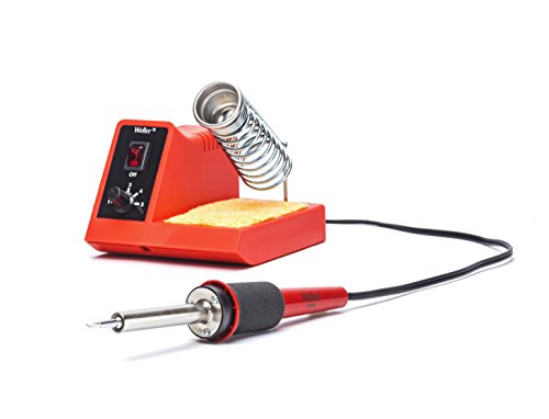
Weller sold out and fell to selling chinesium quality products (with chinesium support levels too) a few years ago, wrecking their reputation.
Today I'd get a KSGER T12.
The more circuits you study and the more circuit-descriptions you read and the more circuit-analysis you perform yourself, the better. You'll start to either recognize circuits, or (more often) recognize opportunities to apply an analysis you've already done, to a very similar circuit.
I would guess there are fewer unique subcircuits, than there are keys on a piano. Some day you'll get to the point where you recognize half of them on sight, and will remember how they work and how to analyze them. Then eventually you'll recognize 85% of them, and one day, 95% of them.
Ask a circuit designer with grandchildren, "How did you understand brand new circuit X immediately?" and you'll receive the answer: pattern recognition.
You know, ten thousand hours of deliberate practice, etc. etc.
edit- buy this (out of print but wonderful) book. Amazon sells it used: <strong>LINK</strong>.
If you want intricate cutouts and your enclosure is small then consider making your enclosure out of PCBs. Another method would be to have someone laser cut acrylic and stack them up to form an enclosure. Example
Try Copper Foil Tape with Double-Sided Conductive Material to connect your wires to the flexible plastic layer and especially the conductor. EMI Shielding,Stained Glass,Soldering,Electrical Repairs ,Paper Circuits,Grounding https://amazon.com/dp/B01MR5DSCM/
QUCS works well, but isn't SPICE
ngspice works as well, but you would probably want some GUI frontend. I think QUCS can use ngspice, the latest KiCAD can as well, and many others: http://ngspice.sourceforge.net/resources.html#GUIs
If you don't need high precision you can always use a simple diode DC restoration and a voltage divider.
You can choose the capacitor value depending on your input signal frequency, the 1.2k resistor value affects the "0V" offset of the output, you can tweak it to achieve proper 0V with your designated signal.
If you want full amplitude on the input, just skip the voltage divider (replace with a single eg. 22k resistor and take the output of off the capacitor diode node.
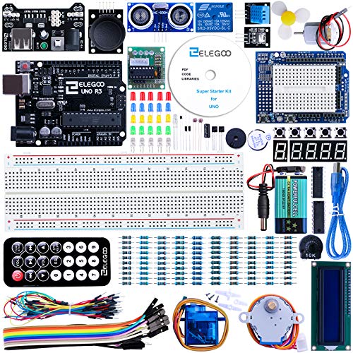
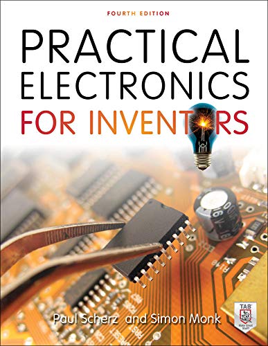
Practical Electronics for Inventors is an absolutely brilliant electronics book. Thousands of well written simplified explanations of useful circuits and how things work. As far as getting started, here is a link to a very full arduino starter kit including a breadboard and a ton of basic components. I didn’t look too closely at the parts list, but it looks like there’s some 2N2222 BJTs in there so that opens you up to all sorts of amplification and switching designs. Best of luck to you
Amazon still allows listings for things that don't actually exist, like black strawberry seeds.
If they allow this outright fraud, I doubt they are going to do anything about the many crappy batteries on their site.
Should be fine operationally. Just not gonna click after being melted.. What kind of iron did you use? If it melted it out, I'm guessing you have an $8 iron in one of those kits. They're problematic because they just go to max heat all the time.. The weller wlc100 40-watt was my iron for like 15 years and worked just fine for this kind of bigger stuff (and is like 40 bucks).. Temp control is crucial: https://www.amazon.com/Weller-WLC100-40-Watt-Soldering-Station/dp/B000AS28UC/ref=sr_1_5?dchild=1&keywords=soldering+iron+weller&qid=1597869810&sr=8-5
Your phone can already capture accurate audio-frequency waveforms; you just need the software to display it.
Something like this: https://play.google.com/store/apps/details?id=com.xyz.scope&hl=en_US
...or, you can help him to learn the answer (or the actual process of coming to the answer) instead of just being rude and then acting the pariah?
For instance, you can go like this.
Hey, 4Sken. I found this decent explanation concerning the difference between amps and watts. One factors into the other, but batteries are generally expressed in Amp-hours (Ah).
Anything expressed in Ah is simply a means of saying this is how much capacity the battery has. For instance, if a battery has 2Ah as its capacity, how long it will run depends on how much current the load draws. It basically boils down to "this battery can run at 2 amps for one hour before it will stop."
So a 1A load will run for 2 hours. A 4A load will run for 30 minutes. A 200mA load will run for ten hours.
This is basically what that means.
Take this information and hook it in with the post that /u/myplacedk mentioned, and you can deduce that how long the circuit will run depends on how long the smaller capacity battery will hold up. You can estimate that amount of time by the bit up above I mentioned about amp-hours.
Good luck!
A USB Type C port can optionally output anywhere from 5V to 20V. I've used this portable monitor with my laptop and it works fine with just 5V from the laptop.
If you want to figure out the capabilities of your port, you can get one of these USB PD sniffers and inject a sourcecap packet, which will return a list of voltages and currents the port supports (if it supports any at all).
It's likely that the laptop only supports 5V. It might be documented in the manual.
I love this one: http://www.falstad.com/circuit/
It's online and Java so you can use it from anywhere. It includes lots of sample circuits. It is also fairly accurate. I use it before breadboarding circuits to do some fine-tuning.
Take some photos as you go! Both to show people your success if you succeed, and to have a "where it all went wrong" reference if it should fail. ;)
Depending on how the pads are bonded to the leadframe, the bond-wires might arch up into the top material a fair bit. I hope you have spare chips!
EDIT: this HaD comment seems like a plausible explanation for the series circuit
EDIT 2: Similar idea illustrated (with inductors & capacitors swapped compared to previous explanation).
My original (probably wrong) thoughts:
I haven't done the maths or anything, but I think you could get an effect like this if you put various zener diodes across the switches (ie. it's a diode when turned off), and diodes+resistors across the LEDs. You could probably hide small SMD parts under the LED.
This way each LED would need a certain voltage to turn on (different types of LED have different voltages, or you could use the same type with varying series diodes), but still conduct at lower voltages. The switches would control how much voltage is available to the LED chain.
Now, the problem is that he seems to be able to turn them on/off in any order. I'm not sure that my scheme would guarantee that...
From the picture this looks like it does not have a copper layer.
I have never used these, but from theory, you cannot solder to it, you put components through and connect them with wire on the back side.
Not very nice to work with i assume.
If you have some time, go to amazon and order some prototyping bords like these: https://www.amazon.com/Uxcell-a14041800ux1143-Double-Protoboard-Prototyping/dp/B0166GCD42
This seems most legit. http://www.quora.com/What-does-J-K-in-J-K-flip-flops-the-electronic-circuit-mean-Who-named-it
Some large corporations have a historian. You might place a phone call and see if some white haired retired historian guy at Hughes can add more to it.
Now if you can get the 1969 EDN article, there was more written a year later.
I can't read it in Google books, but lexis-nexis or library.
>Mr. Bolles verified, as had Mr. Lindley, that the nomenclature was an arbitrary choice started by Dr. Eldred Nelson at Hughes in 1949 or 1950.
Your prof might be hinting at jk being named after a berkeley student at the time,... In some love with intern forbidden in the 50s thing... Jim Knapton (JK) of Tektronix
If it never has to pass through airport security, I can vouch for my solution for extra power on my videography and other gadget-heavy endeavors:
https://i.imgur.com/XxcnRvQ.jpg
It's a 12V 14Ah SLA like those found in a large UPS or maybe an electric start lawn tractor. You did say "overkill." No futzing around with lithium charging issues, very forgiving of excessive discharge, plenty of amps for your toys. Makes a good weapon.
I used this buck/boost converter so I can set the output to 12.3V and it will lock it in there regardless of whether the battery is fully charged at 12.8+ or sucked dry at 11.5V. They can be found cheaper, this is just one of the sellers:
Add a couple meters for battery status and output voltage, a power switch and you're good to go.
VFD = vacuum fluorescent display in this context. In other electronics, it means variable frequency drive. I was imagining an analog meter with an induction motor to drive the needle and a sophisticated servo drive circuit to control the needle position, and I thought that sounded crazy.
But some people would do that, although with a stepper motor not an induction motor.
If you want a hardware solution, many microcontrollers can act as USB HID devices, ie, mice or keyboards. See this article, for example. The keystrokes you send depend only on your program.
As for software, you could just write a program on your PC that listens on your serial port, shows the data in real time and also writes it to a file. Pyserial could be helpful if you like Python.
Nope, 3.7V doesn't become 5V all by itself.
You definitely need it.
You need a battery protector module. It appears your charger has only the TP4056 IC on it. Unless there are battery protection ICs on the other side of the board, this will NOT be sufficient to protect it from overdischarge. This module has both the charging IC AND the protection system on it, and as such provides separate output terminals (OUT- and OUT+) which can be connected to the step-up converter. The battery directly connects to B+ and B- and these should be the only ones directly connected to the battery leads, except for the battery gauge module which should be connected via a momentary switch to prevent a constant draw.
This device appears to be what you're looking for.
Only if you want better explosion speed. These modules are not designed with paralleling in mind.
Heatshrink the darn solder joints! If those two come off from the hot glue (which they probably will, hot glue isn't exactly loctite) and touch (if they come loose they will touch since they are that close and stuck together to boot) you'll get a very nice surge of multiple tens of amps, starting a fire at the point of conatct, damaging the batteries (and thus starting another fire at the battery) and possibly melting the entire thing in your pocket.
Here's a starting point http://www.dx.com/p/2-8-lcd-touch-shield-module-for-arduino-leaf-maple-raspberry-pi-blue-318034
the elecfreaks LCDs are great. There are TONS of similar screens on ebay for similarly cheap prices.
> They are actually 3mm or etc but the lingo is 3 mill.
Lingo: The vocabulary or jargon of a particular subject or group of people.
Synonyms: jargon, slang, vernacular
Me, "Hey dog, is it cool if I inform an unitiated bro of the patois of my fellow frogmen?"
You, "What? I am not a dog. Also, temperature has nothing to do with delivering information. If he is your brother, he should have called you instead of posting on reddit. How does a frog post on reddit anyway?"
Use the resistance as half of a voltage divider to convert the resistance at empty to a voltage at empty. Then you can use a schmitt trigger to read the voltage and power the light. Like this (use the resistance slider on the right to adjust the resistance).
A schmitt trigger is great for this kind of application because it has a different "on" voltage than "off" voltage, so the light won't flicker when the fuel level is near the empty line.
You will need to choose the resistors in your voltage divider carefully to match the values the schmitt trigger expects.
If you are trying to make a 'universal 5V limiter' I believe a zener diode is the magic bullet you are looking for. Take a look at an example here: http://www.falstad.com/circuit/. (select Circuits>Diodes>Zener diodes>Voltage Reference)
Edit: Because reasons.
Your biggest problem here is secondary processors talking over each other. The master-slave paradigm exists to ensure that no two devices are talking on the shared line at the same time. Triggering an interrupt on the main device is the least of your problems.
Edit: Here's an example of a multi-master i2c setup: https://www.hackster.io/chipmc/arduino-i2c-multi-master-approach-why-and-how-93f638
You'll likely need something of this complexity to do what you want, media access control is not a simple problem.
No resistor to the speaker modules.
The 5mW laser modules typically don't draw that much current and have a built in resistor.
The potentiometer will be a problem; they aren't rated for that much power and it won't give good control of the LED brightness. Try a small PWM controller module instead.
Is the green light embedded in the power supply or the equipment itself? Sometimes the removable ac power cord gets loose and needs to be shoved back into the power supply for a better connection. Do you have a friend with a meter? Klein brand is trusted. This kit is low cost/high value.
https://smile.amazon.com/dp/B08W1THSM8/
Never ever use a cup of water, it does absolutely nothing except shock the iron tip. The purpose of a sponge is to wipe off the oxide that forms on the tinned tip. The only reason why it's wet in the first place is to keep the sponge from burning. You don't want it to be 'wet' just barely damp enough to prevent the scorching of the sponge. Too much water just sucks the heat right out of your tip which is exactly what you don't want happening when you're about to solder.
I switched over to brass wool and haven't looked back. I occasionally wipe the tip down with a paper towel after it's cooled down to right around when the solder starts to solidify, but be careful with over cleaning you don't want to wipe ALL the solder off the tip or there's a risk of the iron layer on the tip oxidizing which will kill the tip. Generally speaking you want to to make sure there's a thin layer of solder on the iron at all times and only wipe it off as much as is needed to keep that layer from turning brown.
So I would get a brass sponge holder. They're quiet inexpensive.
One of my most favorite must-haves: https://smile.amazon.de/dp/B06VXL9LMX/ref=cm_sw_r_u_apa_glt_i_4MQWZQC5AJ085RCXJ9J0?_encoding=UTF8&psc=1
It is cheaper on AliExpress, Banggood, etc. But the shipping takes much longer I totally love it and it's really useful for a lot of things (LEDs, Capacitors, Resistors, Transistors, etc) And this way you don't need a Multimeter
It's an Infrared receiver cable.
here is an Amazon link to a similar product.
The "steampunk" part is the infrared sensor.
You know how when you touch the input of an audio amplifier with your fingers, you get a blast of 60Hz from the speakers? Your body picks up the 60Hz from the wiring which is in every wall of your house and the amplifier amplifies it, causing that rude sound.
A number of lamp touch controls use this 60Hz pickup (instead of a capacitive sensor) for their operation. You can touch the metal table lamp anywhere to turn it on and of.
You could probably just get a lamp controller and put in a 120vac relay in place of the lamp and have it control whatever you want. It should work fine with the input wire attached to your door knob.
https://www.amazon.com/Lamp-Off-Touch-Control-Switch/dp/B01FI649TI/
Generally speaking no. You want to use some type of flux core solder for electronics. Old school is rosin based flux. something like this There are new no clean flux cored materiel out there. I clean up the rosin with isopropyl and a stiff brush.
Specifically you could maybe use it if you also use a bottle of flux designed for electronics.
BTW do not use plumbers flux as it is acid based and eventually will cause problems.
There is a special tool to remove U.FL connectors
Looks like this: https://www.amazon.com/Hand-Tools-EXTRACTION-TOOL-U-FL-LP-04/dp/B00HKJUW98
You could build a voltage divider out of capacitors instead of resistors. Naturally this only works for higher frequency signals.
You could build a voltage divider out of resistors instead of capacitors. Naturally this only works for lower frequency signals, as /u/speleo_don has remarked.
You could short the output of the capacitive-voltage-divider to the output of the resistive-voltage-divider. This gives a wonderful thing called a compensated attenuator which is the circuit magic that lets your 1 megohm scope probe have 300 MHz bandwidth. It's an excellent two word phrase to use with internet search engines such as DuckDuckGo. Internet searches will lead you to many helpful places including
If you are interested in digital design with a focus on computers, take a look at this video by Ben Eater.
Ben posted an entire video series which goes through building that computer from scratch. He also has an accompanying website. The computer is based on the design laid out in Digital Computer Electronics by Malvino. The book is out of print but you can find a paperback version on Amazon for fairly cheap. In it, you'll learn everything from logic gates and flip flops to building SAP-1 (Simple As Possible computer).
I bought it after seeing that video and wanting to learn about how computers work. It's a phenomenal book that explains things very clearly with as few words as possible. If you are interested at all in computer design, I highly recommend it!
Otherwise, if you are more interested in analog electronics, you can't go wrong with Art of Electronics.
Also, any of Forest Mimms' books are exactly what you are looking for. I started my electronics hobby building 555 timer circuits from this book
Timer, Op Amp, and Optoelectronic Circuits & Projects https://www.amazon.com/dp/0945053290/
You never use potentiometers to directly regulate the power going to any substantial load (which any motor is). You use potentiometers to signal some sort of motor / power controller to regulate the power going to the load.
Most potentiometers have power dissipation ratings of under 1 Watt (and usually much less: 1/10 W to as low as 1/50 W is not uncommon). And as you have observed, while the resistance is usually linear (assuming you're not pushing it outside of its wattage rating) motor RPM is not, and requires a minimum 'threshold' voltage, as /u/trophosphere points out.
So, consider something like this or this one from Amazon (I have no affiliation with either of them). It'll convert the knob turn into a linear-ish PWM signal with which to drive your 3V motor.
Fair point.
I should also have posted a reference to the Black Magic book, which covers this in great detail.
Amazon link: High Speed Digital Design: A Handbook of Black Magic
Though a calibration would be best, at a minimum you need to do some simple tests.
1) Find a battery, measure it's voltage with a digital multimeter, then measure the battery with your scope. Is the DC voltage on the screen reasonably close to the multimeter reading? Turn volts/div knob and check it again at multiple settings.
2) Probe the output on the front panel (next to lower-right corner of display). Is the frequency on the screen reasonably close to the frequency printed on the front of your scope (which I can't read, though I assume it is 1KHz). Turn volts/div knob and check it again at multiple settings.
3) Find or buy a scope probe! Perform above tests again.
4) You should test some other known signals too.
Turbines are the mechanical device for this. Looks like your application is pretty low power draw, so something like this should work.
To measure flow rate, get a flow meter. You can also get cheap ones from amazon.
When you need to power a remote network device, power over Ethernet is pretty useful.
Lapetus Active PoE Splitter Power Over Ethernet 48V to 12V 2A for IEEE802.3at 24Watt https://www.amazon.com/dp/B076X549HH
Amcrest 5-Port POE+ Switch with Metal Housing, 4-Ports POE+ Power Over Ethernet Plus 802.3at 58w (AMPS5E4P-AT-58) https://www.amazon.com/dp/B073V4STQR
One of several options, probably not UL approved: Float the cell at 4.1V and power your 5V circuit from a boost converter right from the cell. At 4.1V it will have a substantially reduced capacity but will have a good lifespan and have plenty of capacity for outages. Source: many of my hand-built solar-powered telemetry installations that use a single unprotected 18650 cell, some going back more than seven years in extreme high and low temperatures. They have a prolonged "outage" every night, and sometimes a week or more when it's cloudy. Solar panel provides up to 250mA charge current at the output of the buck converter.
This boost converter I use has an Iq of 0.5ma in my application and appears to meet your spec of 2 amps (if you believe those numbers):
The UBLOX M8 is limited to 18Hz, but the price is right and I've had really good (but limited) experience with their modules. They cover GPS, GLONASS, BeiDou and Galileo.
18Hz is only 1.86m per update at 120km/h. Your application requires more than that? Is this car/bike powered by a rocket engine?
Possible? Almost certainly. The signals going to the IR LEDs can be demodulated to recover the data stream, fed to a microcontroller, in order to determine the bit pattern relevant to each keypress.
The microcontroller would then be reconfigured with USB keyboard emulator software loaded (eg http://hackaday.com/2012/06/29/turning-an-arduino-into-a-usb-keyboard/). It would take the demodulated IR output, determine which key had been pressed, and then send that key to the emulation software.
How to use ferrite cores: if your wires pick up noise and you can't make your circuit design immune enough to it, you slap a ferrite on the cable. Not enough noise reduction? Just use more ferrite! Here, read this
Glad you got the help you need.
Relatedly (in case you haven't seen it): Do not TIP!
Not trying to be snarky. A lot of people just use components they see referenced a lot, which tend to be old components that aren't as good as what is currently easy to use and available.
For balance the Hack-a-day rebuttal.
Minimum 10 parts, but at $1.27 each. For $12.70 plus shipping you get what you want plus five spares.
Edit: and this, minimum 1000 parts, but only $0.01 each. That's $10, with 999 spares.
Try to understand the question you're asking is akin to "What is a car and what can it do?" What has been provided here(as of my writing this reply) is just the upper layer or two, but the deeper you get the more and more complex it gets. If you're asking "How does a transceiver work under the hood?" Here is a really good article I found: http://hackaday.com/2015/02/02/get-serious-with-amateur-radio-design-build-a-single-sideband-transceiver-from-scratch-part-1/ That's should give you an idea of how complex a topic you're looking at.
Other places to look for answers would be ARRL's website: http://www.arrl.org - ARRL is the biggest ham organization in the U.S. Then there's Reddit's own ham subreddit: /r/amateurradio
You still may have to worry about FCC, but not necessarily certification, and the process is definitely easier and cheaper. I wrote an article about it recently: http://hackaday.com/2016/09/19/preparing-your-product-for-the-fcc/
For WiFi I haven't looked at the landscape lately, but I know there are a few companies that make compact modules. The ESP8266 is really popular and there is a version that is FCC certified already.
You might want to consider starting with the Particle Photon from http://particle.io, which gives you the WiFi and arduino in a small package and makes it easy to program and deploy in large volumes. These guys are AWESOME.
If you're looking for Bluetooth Low Energy, my favorite company for modules is BlueGiga, but they were recently bought by Silicon Labs and renamed the product line to Blue Gecko. Anyway, the BLE113 and BGM113 might be be what you're looking for.
I will probably get people mad at me for this, but the one I use the most at home is a little kit I got off banggood. I started with the Hiland 0-28v 2A power supply, went to my electroinics supplier and but a quality transformer and a case (whoever banggood does have cases as well), and got a IEC Power cord socket w/ switch. A few little changes inside (you can use a 12v fan if you change the regulator from a 24v regulator to a 12v regulator), add your fuse holder on the back and you have a decent little power supply. Some assembly required :)
Oh, and the micro controller on it is a ATMega328p :)
That won't be enough. The problem here is the current. A winch uses a lot of current as it has a huge amount of torque. That’s probably why they recommend a battery. Since car batteries can supply hundreds of amps. The power supply you posted wouldn't be able to power the winch even if there wasn't anything attached to it. You need a real beefy power supply to do it.
Looking around I think you'll probably need max 150A when you have a 2500lb weight attached.
edit: Strange my edit didn't go through. What I wanted to add is that in the PDF it is stated to need 132 A at 12V with a 2500lb load. So you'll want the PSU with 150A (for reserves) DC current capability. Problem is such PSUs are really expensive and quite big. That’s why a battery would be the easiest solution.
edit2: that's really weird. my edit is visible my profile but not in the thread. but whatever, here's the original edit.
> Looking around in the PDF I think you'll probably need max 150A (132A at 12V with 2500lb) when you have a 2500lb weight attached. > > a good car battery is the easiest solution. a 150A 12V DC power supply is very expensive and quite big. >
Here are some good links about inverse current tripping characteristics of circuit breakers:
https://duckduckgo.com/?q=inverse+current+circuit+breakers
Essentially a circuit breaker will trip instantaneously with a short circuit but will delay a bit with just an over current. This will permit inrush current loads such as motors and tungsten lights to come on without tripping.
If you cannot measure it, you cannot troubleshoot it. A clamp on analog ammeter could be of benefit here. I like Amprobes myself. A digital ammeter cannot respond fast enough to track the changing current.
There's PCBmodE. It's produced a few gorgeous boards, but is much more designer intensive than more conventional design. I haven't used it myself, but it apparently lacks many of the niceties that we associate with most layout editors.
Currently at version 3.0
This is where it would be helpful to have a circuit diagram showing how your button is connected.
Check slide 10 here: https://www.slideshare.net/nbroers/building-the-internet-of-things-with-raspberry-pi
It looks like your code has
button_pin_config.pull = GPIO_NO_PUPD;
Which implies you're disabling the internal pull-up/pull-downs (section 8.3.9 / page 152 in the manual)
If you're disabling those, and you don't have an external pull-up/down in your circuit, then you set the pin as input, it'll be floating. That could explain why it triggers the ISR before you press it.
(But seriously use a resistor for the darn leds, even if only 100Ohms or something. Also get a decent charger/management system/protector module for the battery if you like it unexploded. You can get 20 of them for like 6 dollars and they come with the micro usb connector preinstalled, too)
I would not consider it cheating if it behaves identical to a RAM chip, concerning the 7400 CPU.
However, a microcontroller posing as RAM has some huge advantages for debugging, like dumping RAM to a PC or writing a program to RAM over the serial port.
Also cool: using a LED matrix as a real-time memory display. Using this for example.
Not to discourage you, but this is a larger step upward than you might be thinking.
To get you started, check out the BeagleBone and the other Beagle projects. They're using the TI OMAP SoCs, which are more comparable to the RPI system than to standalone ARM CPUs. That will save you a lot of grief. The BB design is OSS and the schematic, layout files, and BOM are all available. Should give you a head start on your own design.
Personally I'd just buy one instead of rolling your own: at $45 they're priced more as educational materials instead of commercial hardware.
You had your power and ground the wrong way around. The red terminal on the battery was connected to the + row on the breadboard, BUT you use the + row like ground. Your LEDs were also the wrong way around.
The fixed version is here: https://circuits.io/circuits/2831398/
When I run the simulation one of the LEDs has a steady on-off and the other ones strobes. There might be other issues but this should be a step in the right direction.
> I want to see when the switch cuts off in the fastest way possible
You can't get any faster than a single transistor. Connect the switch output to the base of an NPN transistor through a 1K resistor. Pull collector high to a second 5V source, separate from the original voltage source. Connect emitter to ground. The desired output is at the collector, will be high when switch is turned off, low otherwise.
Total time from switch cutoff to output going high will be Fall Time + Storage Time parameters given in the transistor datasheet. For 2N3904 it will be 50ns + 250ns = 300ns.
https://en.wikipedia.org/wiki/Hydraulic_analogy is enough for your first six months or so. It's a long way from perfect, and you'll have to abandon it at some point. But for just starting out and understanding the barest basics, it's fairly good.
> why in a parallel circuit the voltage is the same
Why is the pressure the same inside two pipes that are both attached to the outlet of a single pump?
> why a resistance can change the voltage in a point of the circuit
Why does water only dribble out of a pipe filled with gravel, but gush out of a pipe whose inside is clean?
Visualizing the flow of current as if it were water, can sometimes makes these things more intuitive...
A simulator is a good idea too. I wouldn't use LTSpice, though. Or any SPICE. Try http://www.falstad.com/circuit/. It's not perfect, and you can't even trust its results 100% of the time. But as a visualization tool it's fantastic.
So you have a mechanical switch you're sampling once per day?
Use a zener to clamp the ESD, and throw a super low pass filter on it: For example
You'd take your measurement across the cap.
That's called a "decade counter".
If you'd like a really beginners simulator, use the online circuit simulator. If you need anything better yet simple, i have used LT spice IV
Depending on your needs, falstad circuit simulator does wonders for visualizing circuits. If you're looking to incorporate some common IC's it's probably not the best tool to use.
Simulated. Note the importance of the blocking diodes.
Hey man, good work. Using the current divider rule here is the correct way to go about it. I imagine you've got the right answer there judging by the description of your process.
Check out this circuit simulator applet, it's super handy to check your answers on questions like this.
Edit: Removed answers. Will post when OP shows his.
You mean something like this?
Have you tried looking at this applet? It gives a very easy to understand visual representation of current flow in various circuits and you can even build your own!
EDIT: Here is an excellent one showing a simple common-emitter amplifier.