
What are
/r/electronic_circuits'
favorite Products & Services?
From 3.5 billion Reddit comments
The most popular Products mentioned in /r/electronic_circuits:


The most popular Services mentioned in /r/electronic_circuits:
Circuit JS
HackADay
Banggood
Hackster
Instructables
Fritzing
CircuitLab
eBay
Engadget
TinyURL
GearBest
Smallpdf
Groupon
SourceForge
Google Sites
The most popular Android Apps mentioned in /r/electronic_circuits:

The most popular reviews in /r/electronic_circuits:
Anyone looking at this please be aware that this is not his project and is simply a means to get upvotes and karma. He has had multiple posts deleted on this subreddit due to project theft and karma farming. Please downvote this and stop this subreddit from being abused.
Evidence: https://www.hackster.io/hackershack/make-an-autonomous-follow-me-cooler-7ca8bc
That's an excellent solution!
Something like this would fit the bill.
Unfortunately the transformer is just a one-off that came out of a radio receiver so I don't have good specs on it (only the voltages it puts out - I don't even know the current limits so it might not be suitable for what I want), but here it is: http://www.ebay.com/itm/370505842204 But, just based on the two pound weight I suspect it might be able to handle a few amps @ 40VAC. What made me buy it was the 8.3V secondary that would be perfect for a -12V supply (only for RS-232 so it doesn't need to be exact), and the 3.5V secondary that would be workable to provide low current +5V and +15V for gate drive through a boost regulator or something like that.
You're right, I would use schottky diodes if I end up doing it with a normal bridge rectifier, there's just no reason not to at 60hz. If nothing else I would probably use the "self controlled" mosfet bridge I linked above along with a schottky to enforce the current direction, and at least save a fraction of a diode drop. This is kinda a pet project where I'm willing to over-build or over-engineer to learn how things work, but unfortunately I'm more at home with microcontroller programming than complicated circuit design. I'd like to think there's some easy way to use a few transistors and get more fine grained control on those mosfet gates but I have a hard enough time wrapping my head around one transistor at a time.
Another aspect of insanity - I'm going to try and control this power supply from a 16 MIPS 8 bit PIC microcontroller without using any standalone PWM controllers or things like that (except for the internal supplies). I should have enough ADCs to measure voltages with simple resistor dividers and measure high side current with shunt resistors and level shifter chips made for that purpose. The trick will be making that PIC work fast and/or smart enough to keep things in good regulation! I may need to go with large output capacitor banks to reduce ripple.
Is the lid metal? Also, your feed wires may be the cause of the shutdown of the power supply. You should use spark plug wire. Corona can eat through insulation - even if you don't see it... Also, if you can I would solder brass balls to the ends of your wires in the glass jar. I'd ditch that power supply and look at the tesla coil power supplies... You need a good choke and capacitor on the input of the flyback to keep up with the constant 5ma necessary for what you are appearing to accomplish... http://www.instructables.com/id/Tesla-Coils-for-Dummies/
First choice for me is Logisim Its very powerful and fairly easy once you get used to it.
Second choice (or if you don't want to install anything) is Circuit Lab. But costs money if you want it to be useful.
The most simple solution I can see is to use a microswitch that would be activated by the weight of the system sitting on it.
I believe you could use an operational amplifier (op-amp) in comparator mode and a very small value resistor (shunt resistor) wired in series before the positive contact point. I'm not totally sure it would work as intended though, I didn't experiment a lot with op-amps. Assuming the system draws 700mA, 0.1ohm resistor would drop around 0.07V (so the system would see 4.53V instead) and reduce the current by around 10mA, which I think is negligible.
This seemed like a nice little project to do so I made a simulation to check if what I thought could work: The switch is the positive contact, you can click on to simulate the system being connected, the 6.57ohm resistor is the system assuming a charging current of 700mA. Circuit simulation
not sure if this is the right sub but I'm planning on doing an electronic project on my model tree village.
I would like to hang some lights in the branches that come on when it gets dark and is powered by a battery in the green building which is recharged by solar panels on the roof (replacing the fake panels on there now)
I found some panels https://www.amazon.co.uk/dp/B073Y54925/ref=cm_sw_r_cp_apa_glt_fabc_C2HCP4MWF1557RE2M3DH?_encoding=UTF8&psc=1 That are about the right size that might do the job but I need some help with what batteries to use as well as the right led lights and sensor (small as poss) that will power up when it gets dark. Also probably a three way switch for off, sensor and on options.
Any help would be great thanks.
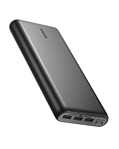
For comparison purposes, here is a well reviewed Power Bank with 26,800mah, for $60. I haven't been able to find a battery with that much capacity for that cheap, and what I did find was much larger in size. I'm assuming they must be using lower discharge, higher supply cells, like 18650's maybe? Not sure.
Edit: I just realized that the common usb charger boards can take as low as 3 volts in, meaning I don't need a 12v supply battery at all, if I custom make the outputs rather than buying car chargers. This means I can run a bunch of single lithium cells in parallel - getting me bigger mah for less money and size. Then there are also charger boards available with build in overcharge protection, for charging this custom pack.
Edit Again: For anyone interested, I priced the whole thing out. To match(or beat) that linked power bank, I'd need 8 Sanyo NCR18650s (10amp cells, $6 each). Add in 3 2 amp charger output boards (again, to match) and a couple input charge boards from amazon, and you are at almost exactly the same price as the premade item. Kinda sucks, I was thinking I could get way more for my money - I guess the prices are reasonable.
You probably also have local maker/computer stores that sell it. Look for the type of place that sells Arduinos or Raspberry Pis. You can also order from Digi-Key, Mouser, etc. Fry's also sells it, but unless you live near one, it's unlikely to beat Amazon Prime.
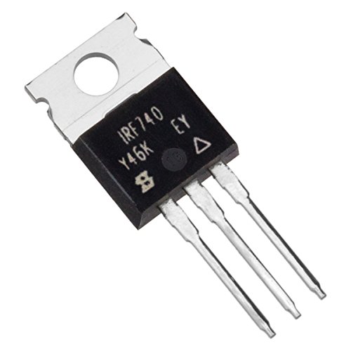
First: Any time you are searching for a component, post a piture of the side with the label. There will be a model number on there that will help you.
You need an LCD controller board also called an "LCD Driver". It will be Something Like This. Search the model number and "LCD controller" to see if there is one available.
Right, OP you're coming from this backwards for 90% of cases.
Get a buck converter that outputs 12V at your required current from a 24V or 48V source. Random cheapo option
There are some cases where you truly do want to redesign a circuit. If that's true in this case, it's a case-by-case and part-by-part assessment, so you really need to post an actual schematic if you want help with it.
This contactor will do three phase up to 25 horsepower.
Apply 24 volts between A1 and A2, it'll connect the three inputs to the three outputs.
These are not normally $2 each, around $50 is average for this sort of thing, so it's a good deal. It'll only provide on/off capability. If you want speed control, you'll need a variable frequency drive, which run about $150 but could be more or less depending on the horsepower (wattage) of your motor.
I think you're totally right about the 3 packages. The LHT7 being an LTC4054 lithium battery charger IC, the 3 pin package being a MOSFET or transistor and the 6 pin being a microcontroller.
You can absolutely run an ultrasonic sprayer with an attiny13 and a 3-5v power source. The circuit to drive the piezo is very straightforward. You can see examples by searching for "diy humidifier schematic" and stuff. It's basically a PWM of about 113khz coming out of the micro hooked up to the mosfet which is flipping on an off a connection from v+ through the inductor to the piezo to ground.
Check out GreatScott's video on a similar cheap board that he reverse engineers: https://www.youtube.com/watch?v=OOZi3QnnDCo
If your goal is to make a motion activated sprayer maybe using this board isn't ideal, with it's timeout and stuff (unless that's a desired feature). There are a bunch of other boards on Amazon and AliExpress that seem like they simply turn on when the button is pushed and turn off when not pushed. You could tap into this with a simple GPIO of your micro and use the driver board mostly as-is. Just search for "5v humidifier circuit board" for something like https://www.amazon.com/Acxico-Humidifier-Purifier-Circuit-Atomization/dp/B09GFPWNX9/
But you could totally just use the board you have and drive that pin yourself with a separate microcontroller too. Good luck in your project!
Immersion heating element is probably the best choice. You can get them in various power ratings.
You'll also need a temperature controller to hold the water at 180F.
As far as energy usage, obviously 150Wh per hour with that 150W element I linked, but it's unlikely it will be on 100% duty cycle, so the best option is some real world testing with a Wh meter and the actual 1L of water being heated.
All you need is a headphone splitter and extension cable. Take the plug out of the monitor, split it and run the other feed to your new speaker.
​
Bingo bango and you've got sound baby!
Your OP says "small ICs or chips" but in the comment you say "small AC board". Please clarify.
If you're looking for a device that measures low resistances then search for ESR Meter. One such device is here: https://www.amazon.com/dp/B00GYSFOM6/
If the extra two digits won't bother you (can cover them as well) then connect one of these mini voltmeters to the output of the potentiometer, then adjust the input voltage to sweep between 0V and 9V.
It comes from a saregama carvaan
You are correct it used to have a micro USB port that was faulty.
It’s got the same ports as this one
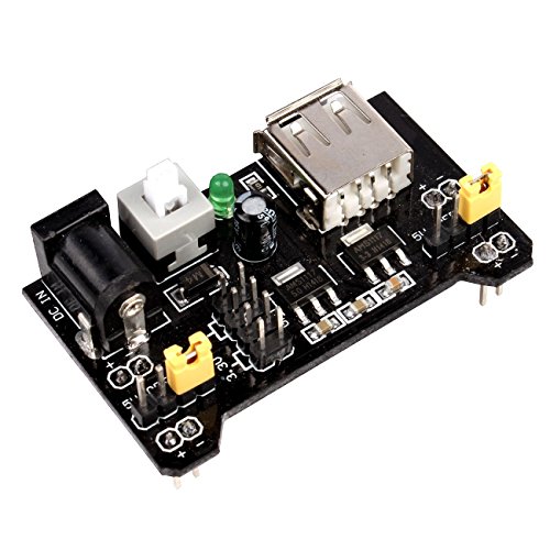
Electronic Spices USB Mobile Phone Power Bank Charger Module PCB Board 5v 1a for 18650 Battery (1 USB) https://www.amazon.in/dp/B09JWN9NDG/ref=cm_sw_r_cp_api_i_Q9140F1CM0DTC4DZNHYV?_encoding=UTF8&psc=1
DPDT relay. I was going to suggest controlling it with a digital I/O from the PLC so you know which signal you're measuring, but if you truly only need to know the max and not which source the max is from, I suppose automatic switching works.
Honestly I can't get through the Engrish on this page but something like this might do what you want.
"DPDT timer relay" is a good search term.
There's a part number listed on the aliexpress page. "MSK-12C02". Searching this part number brings up a few options including amazon:
https://www.amazon.com/pieces-MSK-12C02-micro-small-Switch/dp/B07SJWWYZP
I wasn't really sure which relay board you were linking. I searched the one that pops up in the window on the right hand side. If you're stateside, Amazon has some.
Wow i have to say thanks for this information very insightful. Yes all 3 lipo batteries are the same and charge. my plan was to run this to 2 ESCs via this item https://www.banggood.com/XT60-Connector-1-Male-2-Female-Parallel-Connection-Cable-p-77397.html?rmmds=myorder&cur_warehouse=CN Thanks again- Rustmate
This is the kinda thing I'm wanting to wire myself (or buy pre-made if I can find one with a small enough PCB).
Might as well fully explain what I'm trying to do. Got a cheap Chinese tablet off the Bay, with the intention of using it as a portable Steam machine for low GFX/indie games. Bought an iPega 9023 as I liked the way it cradled the device. Quickly discovered however that there's an issue with the bluetooth on my tablet which means that using a controller causes a massive drop in frame rate (Stardew Valley for example normally runs at 59/60fps, but as soon as I start moving the analog sticks or pressing buttons, this drops down as low as mid 30s). Tried with another BT pad just to make sure (8bitdo SNES style) and got the same result. Using a wired controller is perfectly fine however.
Decided to crack open the iPega and found that there's enough space to fit a USB-C plug along with an Arduino (there are actually test points on the iPega PCB for every button and stick axis). Just need to dremel out a space for the USB-C plug, fix it in place with Sugru, and wire up the PCB. I'm pretty sure that there isn't enough space to fit the innards of a USB-C charger/hub though, so I was hoping I'd be able to wire this myself, but it sounds like it's going to be very tricky to pull off.
>at the MOSFETs (which need to be at 3-5V).
What do you mean by this? Are you talking Vds or Vgs? What's the part number of the MOSFET you're using?
FYI - you can export your Falstad's as a link
Like perfboard but way cheaper? here or here
They're actually pretty damn close to perfboard if you ignore some screen printing glitches and crappy tolerance on the mounting holes.
Another idea, some kind of non-conductive screening that won't melt/burn under solder heat. Can't think of anything really good like that specifically, maybe plain cotton fabric if you're careful about soldering temp. But it won't be rigid unless you add an extra frame on it.
I'd say just go with perfboard. Even non-plated perfboard would work alright for this purpose - just wind the leads together a couple turns and solder them, it should hold fine.
Here's a model :
http://www.spectrum-soft.com/news/winter99/sparkgap.shtm
A discussion about some thesis's with more model :
https://sourceforge.net/p/qucs/mailman/message/31963182/
The model I linked is rather naive, real gaps will depend on dV/dt, have a lot of random jitter etc. Also real Marx generators often benefit from UV from the previous gap speeding up the next gap.
Many Spice simulators seem to really dislike these kinds of circuits. Should Proteus fail to converge maybe try some other ones (I quite like Simetrix).
No. The RockSeed RS310P appears to be a single-channel power supply, so you would need two of them to provide both +12V and -12V. The alternatives are: to build your own bipolar power supply, select a 2-channel power supply instead, or use the single-channel supply set to 24V, in combination with a rail-splitter (virtual ground) circuit.
Hi guys, I need quick help, I broke a proximity sensor from my boss Bobcat and I need to change It before he notices it, I need the one with code 992AA12AP-A2 (see photo) but I can't find it... I found one on Amazon but I dont know if is interchangable, can you help me? This Is the link:
You can calculate voltage and current from the power rating at a given impedance. For 60V and 15A you'd want an amplifier that can do 900W RMS @ 4 ohms.
You'll need to over rate things for continuous usage I'd imagine as well, if you want ~900W you'll probably be looking for an amplifier that can push at least 1200W RMS (tested, not their claimed ratings), look for one that has active cooling as well.
Here's a fairly inexpensive option that can just about do 850W RMS @ 4 ohms in testing: https://www.amazon.com/Behringer-Europower-EP4000-Professional-Amplifier/dp/B001U5JFNM/
You can play around with a circuit simulator, such as Falstad's, and edit the circuit as you'd like. Check out "the Ohm's Law example at Falstad". You can edit a wire to show current and/or voltage, edit the source voltage as needed, and add resistors to simulate your breadboard circuit.
Anyway, the breadboard circuit looks good compared to your explanation.
You can edit the components values by double clicking to see the impact of each... Have fun!
I'm using the current saturation to limit the current to the load similar to this circuit: http://www.falstad.com/circuit/e-currentsrc.html
I can change the load in my simulation to 0.1 ohms and the current stays pretty steady.
Video: http://www.youtube.com/watch?v=o9f3BoPnGu0
Falstad simultation (Requires Java). Adjust capacitor value for throbbing rate. Here it's purposefully lowered for the simulation. IRL, use 100-330 µF.
It's probably not what you've got, but 3-pin electrolytic capacitors do exist. I've got an old tube amp with one of these dual caps separately decoupling the tube bias rail, and the output transformer.
Schematic - the dual cap is labelled C1_A and C1_B
You might be able to find something ready made.
This runs at 10v, but you may find something similar for 6v
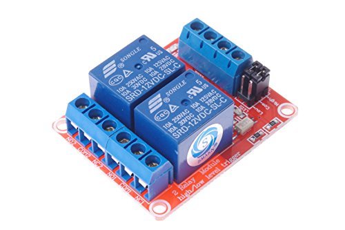
I think the best for this need is using Optocouplers.
They are small and cheap and there are boards of four, like your diagram.
An optocoupler acts as a switch that connects one circuit (your remote control button) completely isolated from the other one (the one that you power with the micro controller)
Someone suggested Relays, but is not necessary in this case.
I checked the no load voltage and was quite close to 13, not too much I think.
These are the fans https://www.amazon.it/gp/product/B08HLNPN53/ref=ppx_yo_dt_b_asin_title_o06_s00?ie=UTF8&psc=1
In that case, i found this pre made circuit that does the same thing, all in one. Attach the power supply on off to the NO and COM, power to the power in, and the switch to the white connector.
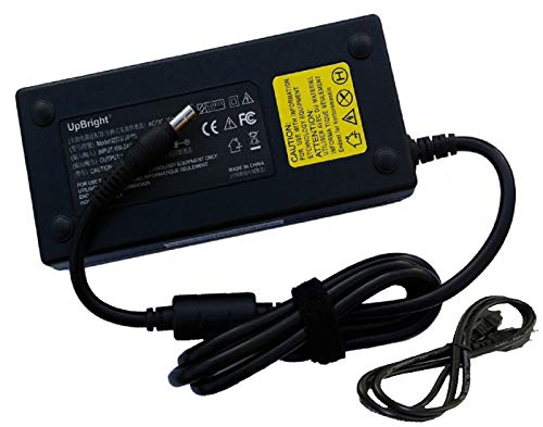
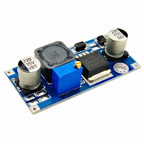
Like /u/Valueduser and /u/shikkonin said, the 48v phantom power doesn't provide enough power to really do what you're thinking about, but you could do something with a DC-DC converter and bring 48v to whatever voltage you need.
The best option would be to use a wall wort or a dedicated supply. I've used these for many projects, however the power isn't super clean. https://www.amazon.com/Aceirmc-XL6009-Adjustable-Converter-Voltage/dp/B081YM993Z/
Does something like that make sense to make it easier and quicker? https://www.amazon.de/SONICAKE-5-Way-Right-Guitar-Pedals/dp/B07L8VBR7P/ref=sr_1_3?__mk_de_DE=%C3%85M%C3%85%C5%BD%C3%95%C3%91&dchild=1&keywords=9v%2Bsplitter&qid=1619463858&sr=8-3&th=1
ACEIRMC 10pcs 12v Relay Board for Raspberry Arduino Relay Module 1 Channel Opto-Isolated High or Low Level Trigger (12V) https://smile.amazon.com/dp/B088W75NZB/ref=cm_sw_r_cp_api_glt_fabc_FYBHHWFCQ8JKVXJ2V7C9
If the wax paper ends up distorting too much, and you're ok with an amazon purchase, try looking up "Theatrical Gel" - something like this:
The name is a bit confusing - It's just tinted transparent plastic that's designed to cut down on light output. You could get a variety sampler like above, and try different colors to find the one that blocks the right amount of the green laser.
I'd definitely say this would be your easier answer than electronics modification or software, especially not knowing what the internals are really doing.
Well, fine for old movies. For nearly the same $, you could get this
Thanks for the detailed answer. I edited my original post to add a detail which is that the bulbs will be spread out and each bulb will need a power source.
I see inverters as low as 17 on amazon (https://www.amazon.com/BESTEK-Inverter-Converter-Adapter-Thinner/dp/B07DVXNSDH/) but if possible i rather do my own circuit so I can personalize the whole thing with the theme of the party.
To be more specific, what im thinking is "if something like that can be sold for $17 bucks I should be able to do something similar for half the price".
Okay then I think what I'd suggest is use one of these cheap float switches which are just contacts. They can be configured as normally open (NO) or normally closed (NC). The switch is only rated for 0.5 amperes so can not by itself support the current for the shop vac motor, so instead you use the float switch in NC mode to drive only the coil of a good-sized relay which will disconnect power from the motor when the float switch goes from closed to open state on high water level, which cuts coil power on the relay.
If the shop vac has a push-action stop button separate from the main power toggle, then find out how that's wired and figure out whether the float switch can be wired in series or parallel to that button.
> Why are you looking at parts to create a motor? Buy a motor.
Ok. I don't mean make a motor. My mistake on that part. I meant assembling the circuit that will run the motor.
> They certainly DO have prebuilt motors. That's how most motors are sold.
In fact, look at this Amazon listing. There they sell SIX motors together with various random junk for a cheap price.
I actually looked at that, but the problem is it enough to run the coin sorter?
>If you are asking about motors with integrated speed controllers, they are readily available as well. just not for under $30.
I see.
> Got lost WHERE?
Which parts is enough to run a motor. Eventually, I get the nuances now. Just now how each parts will work.
> Why the heck would you think a controller for an AV mains motor would work for a battery-powered DC one? Did you even look at the description?
>Which part of that spells 9V DC to you?
>THIS is what a low voltage DC speed controller looks like. And you even get three more in the pack when you blow it up.
I see.
Hey, I am new to this. Soo, thanks for the help. I guess.
This Switch is listed as 1NO but so was the original switch I bought. The shape of this switch is important. It uses on/off and not open/close in its description as well.
>normally open
That means release is off and push and hold is on? The switch I ordered says it is push and hold for on and release for off. It just works backwards.
Depending on what you need to playback on, and how eager you are to build it yourself, triggered digital announcement devices are available. We've considered the same thing, for emergency warnings, etc, via the PA system at work.
Going just on what you've said in your post, Power is Voltage multiplied by Current, so 12V * 12A gives you 144 watts. Computer psu's have different current ratings for the different voltages they supply, so you mostly want to look at current ratings.
IMPORTANT: If you connect the strips end to end you can draw more current then the strip's themselves can handle, so make sure you check out how long they can be, or connect to each strip with a cable that can handle the current you're going to be putting through it.
Do you want to have 5 meters, or 15 * 5 meters = 75 meters? Cause that would be some serious lighting.
https://www.amazon.ca/Switching-Supply-110-240vAC-PicoPSU-Compatible/dp/B007XVD452 or https://www.amazon.ca/LETOUR-Converter-200Watts-Adapter-Lighting/dp/B01HO76O0G/ref=sr_1_11 might do you.
This might be a perfect fit: https://www.amazon.com/Cobra-1200W-300A-Jump-Starter/dp/B0040TEA8K/ref=sr_1_15?s=automotive&ie=UTF8&qid=1491540127&sr=1-15&keywords=emergency+jump+starter+inverter
But I'm not sure if it has enough capacity. (probably not, since they crammed a compressor in there)
One, buy a pair of slippers.
Two, they sell heated mats. Even at box home improvement stores for $20. Not sure why you are incapable of googling warming pad or heated mat.... I'd go for a pet warmer. https://www.amazon.com/Generic-Electric-Heating-Waterproof-Whelping/dp/B0146W6E1G
They sell much more expensive systems with a thermostat control, but you are paying $1-$2 per watt. So a few hundred dollars for a heated bath mat.
One problem you might encounter is lack of outlet near the floor in a bathroom. Hopefully you plug this into a GFCI outlet however you do it.
Great, thank you!
I ordered this Mosfet from Amazon that will be here Tuesday.
Looking at my little "electronics fun kit" I purchased I do think I have one already though. It's called PN2222 and looks just like the "2N7000" when I searched for that.
If this will work then I am good to go! Otherwise I should get the part on Tuesday. 100% fine with not needing the relay, it takes up a ton of room on the board anyway.
Hello!
Welcome to the wonderful world of electronics. Its scary at first, but lots of fun once you get started.
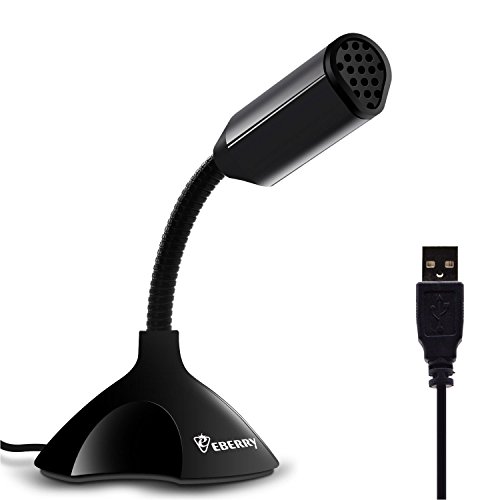
The device you have linked too is a Microphone that is designed to work with "tiny" computers called Microcontrollers. It would be possible to attach it to a "computer" but that isnt what it is designed for.
Sparkfun Links to an example project that uses this microphone, to control some LED's -> https://negativeacknowledge.com/2008/06/11/final-lightbar-controller/
If thats not the kind of thing you are trying to do:
- Could you explain what it is you are trying to achieve.
- Why is something like a Cheap USB Microphone http://www.amazon.com/dp/B00UZY2YQE/ Not what your looking for?
If that is what you are trying to do... well we will come to how best to achieve that when we know what it is your trying to achieve :)
Thanks for the reply. Due to my newness to understanding circuits, understanding circuit diagrams is even more limited but I will attempt to figure out your example diagram. For others interested, this is the relay board I am using: link.
Is this (Imgur) the integrated diode you are referring to?
Also, since I'm not 100% clear on your diagram yet, would installing the diodes in the way I originally asked about be adequate for protection if the relay board did not have integrated diodes?