
What are
/r/synthdiy's
favorite Products & Services?
From 3.5 billion Reddit comments
The most popular Products mentioned in /r/synthdiy:


The most popular Services mentioned in /r/synthdiy:
Circuit JS
Hackster
Cults.
Autodesk Tinkercad
CircuitLab
Banggood
HackADay
iCircuit
Creative Commons
Csound
IGTV
Affinity Designer
FreeCAD
TinyLetter
LTspice
The most popular Android Apps mentioned in /r/synthdiy:

The most popular VPNs mentioned in /r/synthdiy:
The most popular reviews in /r/synthdiy:
If you don't need high precision you can always use a simple diode DC restoration and a voltage divider.
You can choose the capacitor value depending on your input signal frequency, the 1.2k resistor value affects the "0V" offset of the output, you can tweak it to achieve proper 0V with your designated signal.
If you want full amplitude on the input, just skip the voltage divider (replace with a single eg. 22k resistor and take the output of off the capacitor diode node.
This is pretty good for trying stuff out. Note that you should not rely on it for testing exactly how something will work - as with any simulator, it will not behave exactly like the real thing - but it'll let you see in "slow motion" how circuits you draw behave.
I suggest getting a resistor kit off amazon or similar.
https://www.amazon.com/Resistor-Assorted-Resistors-Assortment-Experiments/dp/B07L851T3V/
Then you only have to order resistors if you run out of a particular value, and you will probable have the odd ball if you need it.
Though when I built the TH 555 VCO I had to order some stupid strange value like 137k or some nonsense.
>And then, this just occured to me, but there must be software for playing with circuits virtually yeah?
Yeah! A beginner friendly one is this simulator at falstad.com.
You can click through the example circuits, mess with them and see what's going on with each component. It's faster than swapping components on a breadboard and gives you a lot of info/feedback without needing to own/learn a 'scop.
Hi, i improved the arduino quantizer from hagiwo in some ways 🙂 wanted to share my progress so far, it now has lots of new very musical and usable features and a calibratable buffered output:
Scale Modes: The Scale is chosen by turning the Encoder Knob:
Chromatic Major Major Pentatonic Major Pentatonic + 7 Natural Minor Minor Pentatonic Octaves Root Modes: The Root-Note is Selected by turning the same Encoder Knob while held pressed down! With the Rotate function All Scales are availiable from C, C-sharp, D, D-Sharp, E .... A, A-Sharp, B. So no need to transpose your oscillator anymore! Every Scale Mode is availiable with every Root Note Selected!
CV-Modes: The CV-Mode is chosen by double clicking (and holding) the encoder button and turning the knob while pressed! CV-modes determin what the Mode CV input does:
Control Slide Function via CV (ON or OFF) Control Slide Time via CV, in addition to what is set on the Slide Knob Select the Scales via CV Select the Root Note via CV Transpose the incoming Pitch CV in Semitone-Steps Transpose the incoming Pitch CV in Fifths (7 Semitones) Transpose the incoming Pitch CV in Octaves (12 Semitones) TB-303 type Slide Function with Knob!
Encoder with Switch to select everything
A RGB LED to indicate the selected Scale. And in addition the Root, and CV Mode, when it is in the corresponding select mode.
Pitch CV Input Mode CV Input for all the additional CV functions Gate/Trigger Output Quantized Pitch CV Output
Toggle Switch to activate and deactivate current selected CV_Mode
Buffered Output with Scale trimpot for calibraion!
Inputs safe for Eurorack levels.
Hope you like it!
Code and High res Schematic availiable here:
As it says in the title I want to thank r/synthdiy for all those inspirations and wonderful posts. I do comment a bit but am mostly a lurker. So I figured after about 9 months of reading every post I'm gonna post this. My accomplishments.
If you are interested ask away I'll try to explain or link whatever.
The boxes are described in the pictures and the modular is from left to right:
Passive mult (4x) and 2 attenuators
3340 VCO (submodule on stripboard)
Dual Vactrol 'VCA'
Buffered Line Out Module
Buffered 3x Mixer
Midi2CV (Arduino Nano)
Buffered Mult 4x
555 LFO /CLK + cd4040 divider
Baby 8 step sequencer
You're not wrong. I'd use epoxy.
Alternately, you can use protoboard (here's an example) and then use screws/standoffs to mount the protoboard to the panel. That's the route I'd take.
Here's an article from Hack-a-day on the Baby10: http://hackaday.com/2016/01/14/oh-baby-baby10-build-a-classic-analog-music-sequencer/
It's a pretty simple design and a good way to learn something about electronics.
Answering to myself (in case someone else is interested): It seems that LTSpice can do this - at least it can export WAV files of the waveform at some point in the circuit.
However, I'm still interested in finding a simulator that could do this live, so I could hear the result immediately. I found LiveSpice, but it seems experimental and hasn't been updated since 2014.
Oh gosh:
Top rack is 9v effects meant for guitar:
3x Anderton Super Tone Control, a state variable filter
2x Tremulus Panneur stereo panning tremolo
2x Disaster Transport Jr, a PT2399 based delay
1x generic karaoke reverb, using Juanito Moore's schematic
2x Split / Mix 3, from tagboardeffects, based on AMZ schematics. 1:3 split and 3:1 mix.
1x Panel Buddy changer for interchanging between 1/2" guitar instrument cable and 1/4" patch cables
Bottom rack is 12V bipolar eurorack power:
2x Thomas Henry VCO1
1x Thomas Henry VCO555
1x Noise Module (mutt made from Rene Schmitz designs, among others)
2x MS20 style filter, using KS20 schematic from Kassutronics
1x Yusynth Quadrature LFO
1x Another TH555VCO
1x Quad VCA, MFOS schematic
1x Yusynth ADSR, striboard layout from
1x Dual Yusynth ADSR, stripboard layout by me
1x 4 channel MIDI to CV / Gate based on a blog post by "Kevin"
1x Buffered mult, it's 2x 1:4 and 1x 1:2
1x Mixer, Niklas Ronnberg schematic, 5:1
I also recently bought an oversized solder mat which has shallow part pockets. It’s better than the old cutting mat I was using.
https://www.amazon.com/gp/product/B074LB3YT5/ref=ppx_yo_dt_b_search_asin_title?ie=UTF8&psc=1
Yeah! It’s in on Amazon VOGURTIME DIY Piano Soldering Project Kit Electronics Solder Practice Kit, Great STEM Project and Gift, Multi-Function https://www.amazon.com/dp/B08H872XCR/ref=cm_sw_r_cp_api_glt_fabc_27SY25SCAJ6V99FQB98A?_encoding=UTF8&psc=1
Your eyes do not deceive you. It is a cardboard box. Just something to hold it up for now. My goal is to make the entire system (except for speaker) homemade. I've been delaying a case build as I've been too excited to build the modules first. I'm looking forward to building a case. My friend also has access to CNC and laser cutting machines so I may get to experiment with those.
The specific power supply I have is the Tekpower TP-3005D-3, linked here: https://www.amazon.com/gp/product/B00HX0UYBK/ref=ppx_yo_dt_b_asin_title_o04_s00?ie=UTF8&psc=1.
It's been working out pretty well so far. I wire it with banana to alligator clips over to a breadboard with lugs (the same one I use to experiment with new designs) then break out from there to the modular bus.
This is the one I have. It can deliver up to two amps.
Any wall wart will say on the back what current it can deliver. Unless you’re saying that you’re using a bare transformer — in which case I would advise you not to. You can pretty easily kill yourself doing that, unless you really know what you’re doing...
Get one of these and peel off 5 cables.
What you’re looking for is female-female jumper cables, the link above is the smallest quantity I could find on amazon.
It can't get much simpler then this:
http://hackaday.com/2015/02/04/logic-noise-sweet-sweet-oscillator-sounds/
one IC and a handful of components and you've got yourself a nice square oscillator.
I've just added some more STLs to my 3D Printed Eurorack Case.
For sale here https://cults3d.com/en/3d-model/gadget/expandable-eurorack-case-blocks
This time I've added some stencils to overlay blank panels. You can print your stencil and blank different colours to get a two toned blank. The pictures above show black stencils on white blanks. I imagine more subtle two tone blanks would look superb. I'm looking forward to replacing those blanks with modules, but I've already blown my budget for this year.
Shout out to /u/fneeb for discovering a bug in one of my STLs last week. Thanks to everyone who has supported my design!
The above images show two 26hp blocks, a 10hp and 0hp block added together to make 62hp case.
That thing is simple, but I've tried building it twice and had literally zero output.
My first project was an oscilloscope (this is probably the best beginner kit right now). With one, you can see what your LFO is doing, then use it with a vactrol to control another just like it with a higher frequency.
If you don't mind getting some digital in your circuit, you can also try out an Auduino granular synth. Making it voltage controlled with vactrols is fun, too!
Decoupling caps are important in analog and digital circuitry. Lets just take a quick look at the digital case:
The idea behind these capacitors (decoupling caps, as they are sometimes referred to) is to provide a lot of current for a short period of time to the ICs that demand it. Having capacitors on power rails is very important when working with digital logic circuits. The fast rising and falling edges of logic chips can create "switching noise" in the power rail.
If you build a digital logic circuit big enough (such as filling up a breadboard or two), it is very likely the circuit will start behaving in unexpected/spurious ways without proper decoupling capacitors. If a bunch of logic gates decide to switch their output states at the same time, this will result in a large current demand for a short period of time. A decoupling capacitor helps to provide that higher current for a short period of time.
Read this article for further insight.
This post from hackaday shows what can go wrong without decoupling caps
Cheers
I use iCircuit a lot, (http://icircuitapp.com) It has its issues, it's not always very accurate and has limited component choices, but it's easy to use and quick to try out some ideas.
iCircuit does this (http://icircuitapp.com) and although I like the app a lot as it has by far the best UI I've come across for this kind of app. It's not all that great in it's simulations and lacks a lot of components. Furthermore it doesn't seem to be in active development anymore.
Some pcbs, like most of the ones sold at www.amazingsynth.com are smd, others are through hole.
It sounds like you want to make your own designs, if you do that you can choose between smd and through hole parts
There are lots of schematics online, this is a good simulator with some examples to play with
http://www.falstad.com/circuit/circuitjs.html
otherwise just type the name of the circuit you're looking for into google + the word schematic, and some circuits will come up.
It was a different brand name but I think this is literally the same device as the one I have. Same color and everything.
The only difference will be the jack sockets! Look Mum No Computer uses full size instrument jacks, while eurorack uses 3.5mm audio jacks like these! https://www.amazon.com/dp/B01GBN1NO6/ref=cm_sw_r_cp_api_glt_fabc_GQKD9NTRA3DMQAN63XKH
Feel free to message me if you need any help or would like to add some other features.
While not exactly synth based, I found the Make: Electronics book a very nice hands-on intro to basic electronics concepts.
https://www.amazon.com/Make-Electronics-Discovery-Charles-Platt/dp/0596153740
And it's already been pointed out but Moritz Klein's YouTube series on VCO's is great. Follow along on a breadboard and you'll be good.
As others have said, use tinned copper bus wire. I used this when building the Serge programmer.
For the short ones going from the jacks and and leds use resistor legs that you cut off.
You can order solid core wire pretty easily online. The key word, as you said, is "solid". The type of wire you have is known as "stranded". If you search Amazon for "22 gauge solid wire", there are a lot of cheap options. You can also get these handy "breadboard jumpers" - I like them for clean breadboard layouts.
$ 1K is plenty, but as other answers have you realizing, you need to know what you want and you need a plan, if you want to stretch that money as far as it will go.
Personally I would avoid AliExpress. Tayda has excellent prices and with very few exceptions, everything that I have bought from them has been totally fine. I like Mouser for anything I can’t get from Tayda.
Some places you can save money and be ok, other places cutting corners will save you a few pennies but you will likely regret it in the long run. You can’t avoid an initial investment in tools and basic supplies and that is not a place to cheap out.
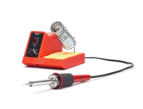
You don’t need a lot to start out. I’ve used this model soldering iron for decades: Weller WLC100 40-Watt Soldering Station https://www.amazon.com/dp/B000AS28UC/ref=cm_sw_r_cp_api_glt_fabc_QVY2BWSRKJTX9CE78RJP?_encoding=UTF8&psc=1, this is good solder and a pound will last you forever: KESTER SOLDER 24-6337-0027 Solder Wire, 63/37 SN/PB, 183°C, 1LB https://www.amazon.com/dp/B00DE2QVIG/ref=cm_sw_r_cp_apip_UdAwkiNWu7B9S. You’ll need wire strippers, little cutting pliers, good needle-nose pliers.
One place you can save money, especially when you are starting out, is in your rack/case. I built mind out of scrap wood and spent literally zero $. My rails are Keva blocks my kids outgrew. Likewise your first power supply. Look up the “MFOS Wall Wart” PSU. if you want to see if the bare-bones DIY approach is for you, you can build one of those from scratch on stripboard for about six bucks, match it with a good AC wall wart and that will support your first several models. You also could as spend just a bit more and make one on a PCB from AI Synthesis and see if that approach suits you better.
Pots, knobs, jacks, and cables always add up. There’s only so little you can spend and still have a satisfying product but you probably won’t have to spend very much at least to know how far you want to take this.
> I'll look into the TS100 as well.
When considering the TS100 remember that you'll get the best performance out of it with a 24v power supply. It will work with lower, but man, mine is a champ running at 24v. And as /u/wolveroony mentioned get the chisel tip for it as well.
If you are building the PSU that Kristian makes, you need AC/AC. I bought this one:
If it works, the dual-trace version of the 647A is probably all the scope you'd need for most hobby projects. I have an ancient B&K 10MHz scope and can't remember the last time I needed something fancier.
Tek scopes are fantastic; that said, that's a really old scope even by Tek standards. I personally wouldn't pay more than $100 for it, but I'm not super-knowledgeable about ancient scope prices.
It's going to take a couple of hours and some equipment to test this device reasonably. Ideally, you'll be able to borrow a >100MHz signal generator from someone. You'll want to make sure that every knob and button individually works over its full range, and you'll want to measure some known sinusoids from the signal generator to make sure they read right. Given the age of this device, you really can't be too careful about checking it out.
You can get a 100MHz off-brand digital storage scope new for a little over $200: here's the Hantek at $234. You can also get a low-bandwidth digital scope suitable for most audio stuff for $30 or so. A lot depends on what you're hoping to do with the scope now and in the future. Don't underestimate the value of being able to capture a signal in memory and analyze it.
Best of luck in your scope purchasing adventure!
This is a good reference book and can be found in PDF format for free on archive.org
Hey! I just got this working on a "pro micro" clone board. It's actually a clone of a Sparkfun Pro Micro, which is basically a Leonardo in a small package. I used the "Ex1.Potentiometer" sketch that comes with the MIDI controller library, added a second potentiometer with one line of code, and I have a joystick controlling Serum's filter cutoff and resonance right now.
This pro micro board was 3/$20 on Amazon. The one from Sparkfun would also work, or a genuine Arduino Due, Zero, Leonardo, or Micro. All those use the ATMega32U4 processor, which has built-in USB and can be configured to be a MIDI USB device. Teensy would work too.
I can give you more specifics if you need them. The only complicated parts are that you need to install two libraries (MIDIController and MidiUSB) and make sure you select the right board (Sparkfun Pro Micro) and processor (these are the 5V version, there's also a 3V version).
Cool idea... Now I need a good joystick to replace this crappy spring-loaded one I'm testing with. :)
I never thought I'd surpass the late Ray Wilson's Make: Analog Synthesizers. Here's a link to my book on Amazon.
Not sure what it is called, in faders I think it's a little more robust, probably silicone rubber. But most electrical tape is dielectric vinyl, which would probably work fine. Just search for some non-adhesive vinyl or cotton tape, (sometimes called "wiring harness tape"). Here's some "dry vinyl" tape on amazon.
Here is a listing on amazon for the same powersupply that was left behind and I was planning on using.
I don't have a scope to test how chinesium the power supply really is. worst case, it blows up and I do it over with a 9v.
​
​
​
​
​
​
It really isn't out of my reach though, I just finished 10 VCOs, 8 effects modules, 4 Buffered mults, and a lot more, all DIY. I already have most of the solar 50 laid out, its very easy. There are 10 identical modules using a simple reverse avalanche transistor that is modified by a set of 5 LDRs circled around a single light source which is powered by an in with a passive attenuator for the input. You then have 5 buttons to enable the modulation per oscilator, 5 push buttons for Muting an oscilator, 5 recangle red lights, 5 pitch pots and on overall pitch, an AR, a gate in, and hold. Besides the AR and reverse avalanche oscillator it just simple parts and I have a few of them already laid out.
I'm not new to making my own modules, and I've used LDRs and vactrols before. But I tested a few out to see how they effected it in a practical point and didn't understand how the terms used related to the properties of the LDR.
Arcade buttons are just a momentary switch with a plastic piece on top. I used these but I swapped the switch itself to these to make a bunch of guitar stutter/telegraph pedals with the option to either always be on with a press cutting signal or always be off with a press allowing signal.
Really any plastic bit that can trigger the switch will work fine (the specific buttons I linked are pretty tall).
STM32F373C.
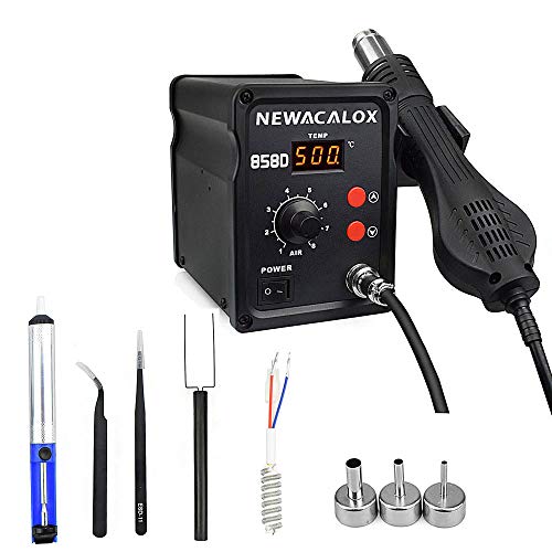
Hot air station is this thing, looks like it's sold out now, probably because it burns down houses or something... Worked just fine for this though, no complaints.
I use these guys with a lot of my prints. I put them on the end of a cheap soldering iron and they slide right in https://www.amazon.com/DYWISHKEY-Knurled-Threaded-Embedment-Assortment/dp/B07MWBJB67/ref=mp_s_a_1_3?dchild=1&keywords=heat+press+threaded+inserts&qid=1597346253&sr=8-3
Would something like the Akai Professional MPX8 work?
Also, in case you didn't notice, it has a big brother, too.
Here's one of my synths: https://play.google.com/store/apps/details?id=com.FormerSpaceMarineSoftware.CircularSound
That uses granular synthesis and waveshaping to make, what I think is some pretty compelling noise. Waveshaping can lead to noise with lots of great character.
I use the brass m2 screws I got with this, or a similar kit: https://www.amazon.com/dp/B07PDQ7DVS/ref=sspa_dk_detail_3?pd_rd_i=B07PK23VC4&pd_rd_w=4u0jL&content-id=amzn1.sym.dd2c6db7-6626-466d-bf04-9570e69a7df0&pf_rd_p=dd2c6db7-6626-466d-bf04-9570e69a7df0&pf_rd_r=C21AGRT9K1WCG9533SHW&pd_r...
If your panel is 1/8 inch the bottom of the screw should clear the slider. If it's thinner than that you can use a small washer to space it.
> , I think? I don't know, I need to take a class on noise in analog circuits, but I want to run hot to prevent the noise floor from being noticeable.
Small Signal Audio Design - Douglas Self - will get you about 80% what you need to know about noise in analog audio circuits. (there are .pdfs out there!)
Minimizing noise is a hallmark of a good analog designer, but it's important to do so where it counts and understand what contributes to the noise. Don't optimize what you can't measure (or simulate) ;>
I agree that they don't make it readily apparent how to change the control range, for me it's easier to change the reference voltage and adjust the resistors. Here is a version that takes +/-10V in. The SSI2130 input currents are polarity protected (from power-on/off glitch) and are limited to 50uA by the 33k resistors. I used silicon diodes to create a wider "dead-bands" to better isolate the individual waveforms. It should be pretty straightforward to add an inverting summing amp to mix in a potentiometer control before the input. There's quite a bit of sensitivity to R10 - 6.65k, but the series didoes should help to clip out some of that...
If you'd rather not build it yourself, you could get one of these.
Really good practice is building stuff on a stripboard. Buffered multiples is a good starting Exercise, built a shaper for shaping white noise into bluish noise and amplifying it and adjusting the filters to help make hats/snares. I spend a lot of time dissecting designs to see how they work, they pulling parts of circuits and putting combinations together.
Do you have a bench supply? I fried several modules by not using one, luckily I could fix all but one (I didn't try the SMD one, I don't enjoy working on SMD much, I'm about to build a clouds module in SMD to get some practice
I use 5528's I bought here - https://www.amazon.com/gp/product/B08QRYD4GR/ref=ppx_yo_dt_b_search_asin_title?ie=UTF8&th=1
Mine are in the Turing Machine vactrol mix extension, but I feel like the application could be similar. The ring a little bit, but work great for the application. I used white LED's, but only because I didn't know green would be better suited.
Whatever you use, look at the "dark resistance" and insert that into your circuit to see if its enough to silence things. Also consider the working resistance range to make sure its suitable to your needed levels.
I don't recall what I used for current limiting the LED, but it was probably 1k or 2k. You just need it to turn on fairly brightly. Sealing it to the sensor is the most important part - any stray light is going to mess things up.
As far as assembling your DIY vactrols, I've fount it saves a lot of space to assemble them vertically instead of axially. The LED legs make a 180 deg bend at the top and there's just a group of four leads in a small little space. They're a little more fragile (like a radial cap), but I haven't had any issue with mine.
I use a little low-profile vise called stickvise. I love it to bits, and I will probably get some teflon jaws for it as well. I also have a larger velleman one similar to the one pictured with the rotating clamps, but I really only use it for desoldering or installing really large components where you need extra clearance.
I’ve got a DIY solution I’ve been super happy with: get half a dozen one-foot lengths of lock line, mount them in a hexagonal pattern on a rectangular piece of 1x12 pine (eg drill holes + epoxy) and top with alligator clips. Gives you an amazingly adaptable holder for all sorts of things. I also have a Panavise, the ubiquitous helping-hands, etc but have never found anything quite as useful/usable as the DIY lock line solution
Edit: I did something like this without the milling etc
What kind of soldering station are you using? Is it feedback temperature controlled? You probably need to practice cleaner soldering skills on some test boards before you mangle another board.
I'm intrigued by this idea of 3 separate small supplies. I see a similar unit to your Alitove here on Amazon JP, ie this. I notice you said 60W, but the Alitove seems to come in 5, 10 and 30W. 10W seems like it would be enough. What do you think?
If you're just jumping in id recommend starting with simpler analog stuff. Skull and circuits is great - Buffered mult, attenuverter, lfo. Learning how to set up opamps and what all components do in an opamp circuit is like half the battle.
Your power entry module will probably have 0.250” tabs with wires with spade terminals soldered to them, according to that photo. I would not buy that particular module but instead one without the silly wires, then crimp fully insulated (like these) quick disconnect terminals onto the wires from the splitter, after cutting off the plug and carefully stripping the jacket, then the wires. Going further, if there’s any exposed metal anywhere with the potential for any high voltage on it, I would cover it with a physical shield to prevent any accidents from fat fingers poking around with the unit plugged in.
But I’m known for going kind of overboard with high-voltage safety. Here’s something I did for someone else; that’s just the power entry cover and I did another over the power supply terminal block.
Here's all the parts I ordered from Mouser. I'd cross-reference with the official MI BOM, as there are likely quantities that are different/missing for common parts (some I had, some I get extra for the discount), but for ICs and such this should take care of you. Of course I make no warranties, etc.
I needed to order the following parts separate:
V2164D IC
PDT switch PCB mount
3.5mm jack PCB mount (I used this)
And I couldn't find an Atmega328 in a DIP format anywhere, I ended up cannibalizing one from an Ambika voicecard I'm not using.
Hope this helps!
I'm using M3 screws, and they fit standard module holes without any need for drilling out. M3 is a metric standard - the shaft of the screw is 3mm wide. They're about 12mm long. I get them from a local hardware store, but here's the closest thing I could find on Amazon US. (Haven't actually used the Amazon ones, but they look the same).
Attenuverters. Buffered Mults. Both simple op amp stuff. Mutable's Shades is a good template for attenuverters. For both, I would suggest integrating bipolar LEDs. I use the ones in my mults just to visualize modulation or triggers sometimes. And blinky lights are just fun to look at.
Kingbright has a nice variety of two lead bipolar LED's in a few different color pairings. You can design for 3 lead ones easily enough, but the two lead ones are a little simpler.
If you want to go bigger, I would start looking at designs from Yusynth, Music From Outerspace, and Kassutronics. The CGS versions of Serge modules are also a good source of ideas. I'd just go with what you need. VCA, VCO, VCF, ADSR.
Music Thing Modular also has some cool stuff. Not the biggest range or modules, but some really fun stuff. Radio Music is a favorite of mine, but unfortunately the Teensy has been delayed into oblivion for a while... There are a couple of cool EQ's and an overdrive and other stuff too.
If anything seems to complicated, there's no shame in going with kits. Makes hunting parts down a lot easier. Befaco boards can be crowded, but they have some great modules in my opinion. Erica's DIY line looks really cool too. Kassutronics, and Music Thing are also available as kits. Synthcube and Thonk are both good places to browse the available kits.
Tomato_Basils solution solves all your problems.
And if those little adapters still get lost, then hot-glue them to the device. :-)
I've posted lengthy lessons on soldering as commentary on half a dozen posts over the years and you'd think I'd be smart enough to copy and paste it somewhere after the first couple but no. If you want to post any pics of your work here I'd be happy to give you feedback.
Also(and especially with SMT stuff that you're reflowing with hot air), I recommend no-clean liquid flux. Just a few drops and some hot air, and when all the pads reflow, a few gentle taps on the board with your tweezers to help the IC overcome the coefficient of static friction and surface tension will pull it into place as if it were placed in a manufacturing process by a machine.
Should work okay.
Personally I'd rather use one like this as it gives me greater flexibility in the input and output voltages I can use.
Looking to retouch the faceplate of my Sequential Circuits Pro One synth. As you can see, due to lots of use the paint around the switches has been completely worn off.
The previous owner tried to paint over the metal with either black paint or a sharpie, but it stands out massively from the surrounding paint and comes off pretty easily itself.
Biggest problem is that the original paint is kind of textured, as you can see from the pic.
​
My current options are:
​
- Touch up using plain black acrylic paint, followed by a satin varnish over the whole front plate to protect it and hide any inconsistency in colour.
- Use some kind of textured, black spray paint like this: https://www.amazon.co.uk/Structure-Bumper-TEXTURED-Plastic-DRYING/dp/B019WSCO86/ref=asc_df_B019WSCO86/?tag=googshopuk-21&linkCode=df0&hvadid=218093857332&hvpos=&hvnetw=g&hvrand=1498714096922013798&hvpone=&hvptwo=&hvqmt=&hvdev=c&hvdvcmdl=&hvlocint=&hvlocphy=1007009&hvtargid=pla-730992373874&psc=1
- Strip the entire thing and take it to a screen printer to be redone from scratch.
​
What are people's thoughts? Would it be sacrilege to strip off the original text and paint?
​
How would you approach it if you were in my shoes?
Agreed, I do like the size of the ones you posted. Arcade buttons can be pretty massive. I've been looking for a way to use some recycled Playstation 3 controller buttons. So far they've worked ok with these buttons, but they're too clicky. I think I'm going to try them with these. They're a bit of a pain either way, in regards to mounting. But I'm mounting the buttons on a PCB and using the PS3 buttons as a cap.
Anyway, happy modding! Keep it up!
Cool I'll check those out. I prefer 24mm Sanwa arcade buttons. They're kind of big but they're fast. They also come in a huge variety of colors.
https://www.amazon.com/Sanwa-OBSF-30-Tournament-Joystick-Compatible/dp/B005CCLYVK?th=1
FYI The first link in your comment is the buttons, not dials
Thanks for the details.
what about wd40 contact cleaner tho? they do one specifically for this but not sure if it’s a bad idea on these pots Contact Cleaner by WD-40 Specialist - Non-conductive Spray Suitable for Use on Sensitive Electronics. Removes Dirt, Dust, and Flux Residue- Smart Straw Narrow, Wide and 360 Spray - 400 ml https://www.amazon.co.uk/dp/B006UCJ5WQ/ref=cm_sw_r_cp_api_i_EQV5WMZMBTEE0NB0JCC3?_encoding=UTF8&psc=1
I like solder suckers - this is the one I have and it’s great in the case where you fill a hole with solder before the component is in, or if you just used too much solder and need to remove some. You do need to clean the nozzle more or less every time you use it or it stops being effective. But I’ve had mine for years and it’s still going strong.
Like the other commenter said, if you need to remove a component the best course of action is usually to just cut all the pins/leads and then remove them one by one (that’s where the solder sucker comes in) You end up destroying the component, but most things cost less than a buck or two so it’s not a huge loss.
For things that are really hard to remove, like jacks, IC sockets or pin headers, I keep some chip quick on hand. It’s basically solder with a much lower melting point, so you can heat up a pin and it will stay liquid for 3-5 seconds while you heat up the other pins. I think it’s made for desoldering SMD components, it’s really good for that. It’s kind of tricky to work with though.
I found a set of caps I'm really loving.. I don't want to mess around with polarity (because my other project is audio) and this was about the only place I could find the larger sizes in ceramic. They are also clearly labeled so there's no messing around with trying to decode the printed value (which is an incomprehensible "system" in the case of caps).
The set I got had cool little poptop containers that were easy to separate and store in my component drawers. I don't see that on the page anymore. Just to show what those containers are like here's a link to a different product.
I use a +-12V psu - (amazon link). It's powered by an old notebook wallwart. Works fine.
Image is just a teaser... I'm looking for a joystick that will provide viariable resistance or voltage to an arduino analog input.
I ordered this guy: https://www.amazon.com/gp/product/B08W52LQPR/ref=ppx_yo_dt_b_search_asin_title?ie=UTF8&psc=1
But it is clearly only on/off switches in each direction. Ideally I'd be able to have control over 2 or 4 axis's with values from 0-127. Thanks!
I recently wired up an MFOS Sound Lab mkII using this 22 AWG stranded. I generally prefer stranded over solid core, as it is more resilient to breaking. I also liked the colors on this set!
That's a fair concern. The reviews of the one I linked to were generally positive but some people did mention wrong values in the caps. Here's one with better overall reviews. In any case, it would be wise to meter the components before use.
You can get bulk sets of components on Amazon pretty cheap. Like this assortment set. Then top it up with specific things you need from a cheap online vendor like Tayda Electronics.
Interesting stuff. Thanks. I just had a look at your post on the Lyra-8 build from last year. Looks like it took a lot of work. Well done. What was the approximate cost at the end of the day? How does it sound?
I wonder if it might be good to put 'acorn nuts' on top of the upside-down bolts you used for the touch sensors. Depending on the length of the bolts, there might still be enough of a shaft to get the alligator clips on while making the tops more finger friendly.
You don’t cut an AC cord ya silly goose. You get:
Amazon Basics Computer Monitor TV Replacement Power Cord - 3-Foot, Black https://www.amazon.com/dp/B072BYGKZW/ref=cm_sw_r_cp_api_glt_i_YC1NX5YCAGBNHQP8EG03?_encoding=UTF8&psc=1
URBEST Inlet Module Plug 5A Fuse Switch Male Power Socket 10A 250V 3 Pin IEC320 C14 https://www.amazon.com/dp/B00ME5YAPK/ref=cm_sw_r_cp_api_glt_i_0HDG2FZAPTJSC4FVKWH1
Check out the wiring on the customer images in number 2.
Alright, I’m not very well versed in modular builds, but I do know some electronics stuff.
If I understand correctly, you’re looking to make connections between two layers in the same module right?
It kind of depends on the distance between them I guess. If they’re quite close you could just go with headers. Otherwise you might look at JST connectors. They come in a variety of sizes, some with 10 pins or more. You can connect them with rainbow ribbon wire to avoid the mess of 30 separate wires
No problem. Something like this:
URBEST Inlet Module Plug 5A Fuse Switch Male Power Socket 10A 250V 3 Pin IEC320 C14 https://www.amazon.com/dp/B00ME5YAPK/ref=cm_sw_r_cp_api_glt_i_0TQ6D9PQD650F1QSKE6V?_encoding=UTF8&psc=1
Look at the customer images to see how to wire it. Don’t hurt yourself
In general:
XX4011YZZ
Where XX is the manufacturer prefix, Y for CMOS will either be B or something else, and ZZ are any suffixes to the part.
XX doesn’t matter for most applications but I have built a few projects where the manufacturer did matter according to the designer. If there are no notes in the build/repair literature, it’s generally safe to use any manufacturer.
B following the part number in the Y position means Buffered outputs. Buffering means the output is beefier to drive bigger loads. Without buffering the chip may be able to drive between 1 and 3 CMOS-only loads; the buffering multiplied that capability by about a factor of 10. Unless something says otherwise, always use buffered parts.
ZZ will be any optional suffixes that may or may not be present, and may be any number of letters and numbers. These usually refer to: 1) Revisions to/improvements made in the basic part design; 2) Temperature ratings, sometimes only present if they are Industrial, Military, or Space-rated parts; 3) Things like lead-free packaging; 4) Packaging options such as DIP, SOIC, TSSOP, etc. 5) Other gibberish the manufacturer includes. Most of the time, except for packaging suffixes which define the physical format of the part, you can substitute any common logic IC with another with any differing ZZ characters.
It’s not true for every part though, for example, PIC, ATMEGA, SAM, and similar processors with differing letters in the part numbers can mean radically different things. Amount of flash, RAM, speed, etc.
If in doubt, always do a search for “(part number) data sheet” and look for what the extra letters mean.
Here’s the book on the 555 I mentioned. I’m pretty sure the author posts here I found it from his posts on reddit.
The Ultimate Beginner's Guide to the 555 Timer: Build the Atari Punk Console and Other Breadboard Electronics Projects https://www.amazon.co.uk/dp/1520148038/ref=cm_sw_r_cp_api_glt_i_XNRY10NYCBB4KFX8EH42
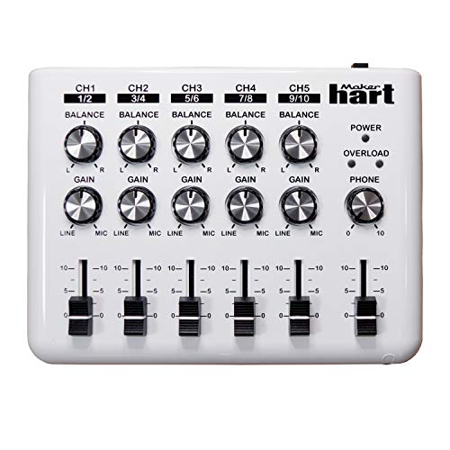
Have ya'll checked out the Maker Heart mixer? Not really the same because there is no EQ but this is a good modern mixer for something like the RD-6. When the gain is increased its a very nicely saturated sound. It's stereo and not mono though and there is no FX bus,
https://www.amazon.com/Maker-Hart-LOOP-MIXER-Portable/dp/B01M68UK38/ref=sr\_1\_4\_sspa
The type of licensing you're describing seems to be a Creative Commons Attribution, Non-Commercial, Sharealike: https://creativecommons.org/licenses/by-nc-sa/3.0/
It'd be up to the original makers to declare their project to be so, which would be complicated for Ray. Luckily, all the way at the bottom of the MFOS homepage it says
> Everything on Music From Outer Space is free for non-commercial use. Please feel free to use the information presented on the MFOS website to the fullest extent for non-commercial uses. You can make your own PCBs from the layouts and drawings we provide or design your own if you prefer. We appreciate a link to us if you blog or YouTube your work.
Which sounds a lot like just CC NC, with the attribution appreciated but not necessary, and sharealike also not required, but encouraged. I am NOT a lawyer and it'd be best to contact his wife to be absolutely certain, but from what's available online I think you'd be ethically in the right to incorporate his designs in a CC BY NC SA work.
The type of licensing you're describing sounds a lot like CC-Attribution-NonCommercial-ShareAlike:
https://creativecommons.org/licenses/by-nc-sa/3.0/
It's an alternative to copyright that has been enforces by some courts around the world. That specific flavor is pretty much exactly what it says it is: users are free to make whatever they want with what's shared, as long as attribution is given to the original creator (just a name and a link qualifies), it's not a money-making commercial endeavor, and whatever changes the user makes are also released under CC BY-NC-SA.
I was really successful using the filtered PWM signal of an atmega. Simple lowpass filter with R = 1k and C = 100n.
Then Op-amp buffering and using one trick makes this thing work: instead of letting the pwm counter count up to the maximum, you reset the counter 239 (range 0 to 240) which results in a resolution of 4 steps per semitone.
I learned this trick from here: https://www.hackster.io/janost/diy-usb-midi-to-cv-0a5469
Thanks so much! Just from an educational standpoint where did you find the specs of the pin? I'm a beginner at electronics and this is my first real project, so I'm not sure if you found that from the schematics themselves or the user manual.
If you have the time would this transformer that the other commenter suggested work?
Buffered is generally preferred because then you know what you're getting for a signal. They are usually current limited.
If you have a datasheet for the USB interface it should tell you the maximum voltage it can handle. It should give a number for maximum input without distortion and a maximum input that won't cause damage.
I was thinking some more about mounting the potentiometers so they were interchangeable, and came up with this:
Using board mounted potentiometers plugged into 5-pin gpio headers. This way I should be able unplug them, and swap values. And the lug nut should keep in snug while it's installed. What do you think?
My only concern is that its not the tightest connection between the potentiometer pins and the connector, but I tested a few and they seemed "good enough" I think.
Here is what helped me: Buy a "bullet journal" which is a notebook with little dots on the paper instead of lines. I have these ones. Then draw out a rectangle which represents your board. We know that all dots horizontally are connected on stripboard, so we can visualize the connections a little more easily here on paper. Draw an X where you need to make a cut and draw out your components so you have an idea of where each part will go. Here is an example of how I drew one
The only caveat to remember is that if you draw your boards top down (which is what I do), you will need to mirror it when cutting traces on the underside. I COULD just plot it out from the underside, but my brain finds that harder.
Those fume absorbers are just okay. I have some name brand ones and even those didn’t absorb much, you can’t expect much from a 6 mm you can see through, but they did a grand job of spreading the remaining noxious smell about my room. Really the best thing is to exhaust the fumes outdoors so you can share the love with your neighbors, but next best is having something with a lot thicker filter and with more layers. Here’s what I use; they’re really marketed towards marijuana growers in the States and you don’t seem to have much similar in the UK. Try searching for “ventilator kit.” Same basic hardware can be used to exhaust outside. Mine pulls solder smoke from over 50 cm away.
As far as lead-free solder, spend the extra 10 quid and get a name brand such as Kester. The reduction in wasted time and frustration will be well worth it. Also remember to change out your soldering tip when switching between leaded and lead-free; the latter doesn’t work well with lead contamination present.
Whether you need to go lead-free depends in part on your sales volume. If you become the next Mutable Instruments you will definitely need to follow RoHS directives to sell in Europe, but generally at low sales volumes you can get an exemption. I’m not a trade lawyer so you should do your own due diligence in these matters.
Get yourself a dispenser like [this one](https://www.amazon.com/dp/B000W9IVBY (wow, that’s double what I paid 4-1/2 years ago) and a roll of 0.015 solder, you’ll be happy even if you’re soldering 0402 components. Just know that for things like pots and jacks you may use up to a foot of solder for each. That’s never bothered me.
If you're up to a bit of very easy SMD soldering then this buck/boost PCB from Banggood is good for powering a module with the advantage of 5V and 3V3 if you want to power an Arduino or ESP32.
It's a PCB front panel with a matte black finish. I made everything in EasyEDA then put in a big order for PCB's and panels. It's a bit tricky making modules this way as you have to line up the main PCB header pins with a pot and jack PCB then line up the pots and jacks on the front panel and get all the spacing right. I've got the 8HP version dimensions spot on now, the first attempt resulted i na green PCB because I forgot to add any solder mask on the top layer.
Buy yourself a DMM. It’s really important if you’re going to keep doing DIY, whether it’s your own builds or you’re putting kits together. You don’t have to spend $100 or more; even the ones they used to give away at Harbor Freight are good enough for basic work (I used one just last night to find an not-quite-shorted MLCC capacitor on a VCO Maximus, quiet a bizarre failure). If you don’t own one yet, something similar to this would be a good choice for price versus features.
When you do a build, it’s always best to not install the ICs if they are socketed until you can do a safety check. First, put your DMM in resistance mode, and check between the +12 and ground power connections, then -12 and ground, then between +12 and -12. As long as you’re not reading below about 200 ohms (depends on the module; it should normally be a very high resistance) you should be safe to apply power to the module. Next, switch to voltage mode, connect the module to power, and check between ground and the supply pins for the ICs. If that looks good, turn off power, populate your ICs, and test functionality. If you built with surface mount, you can exactly plug the ICs in later but do the same tests anyway.
I do have a separate test rack, which has an LFO, Rat King Random which gives a clock and CV, a simple sequencer, a VCO, and an output module with headphone out. It’s powered by a Meanwell RT-65B power supply which gives +12, -12, and +5; I can test just about anything and if something goes wrong, it doesn’t kill my main rack.
I use tinkercad for panels, as it's really easy to make prototypes quickly...
Here is an example of a volca breakout panel I was messing with: https://www.tinkercad.com/things/3Y3be6cHtGj
If anybody wants to use this, here is a link to the Tinkercad file. It can be downloaded directly as an STL. Leaving the link because the design isn't perfect (the middle panel is off center by about .5 mm, but needed to be for my purposes), but it will definitely work right off the printer. Make sure to make your print bed a little hotter because even with the raft setting in Cura, it lifted up a little.
The acrylic bottom and back panel (where the jacks screw into) are required, though I may design a complete set soon.
I hear what you're saying, i do. There are a lot of designs that are, in my opinion, half-assed. I'm not sure i'm sold on spending $1.50 on the microcontroller PLUS $2 on the DAC, when there might be another single chip that does it all for less, OR, there might be a better combination of chips (or another platform) that provides better results.
For those of you who are curious how the PWM can make a CV without the DAC, the answer is LPF. These are the projects i was using as starting points: https://www.hackster.io/janost/diy-good-ol-midi-to-cv-d0e2bf <- This is the article that misled me - he says you can use the ATTiny84 instead of the 85, but then his code uses a register / timer that the '84 doesn't have. Meanwhile, i was really excited about having access to all those IO pins.
https://emalliab.wordpress.com/2019/03/02/attiny85-midi-to-cv/ <- Looks like tidier code, but still doesn't compile on the '84.