
What is Reddit's opinion of
COMSOL Multiphysics?
From 3.5 billion Reddit comments
➔ COMSOL Multiphysics website
By popularity on Reddit, this Service is:
30 reviews of this app found across Reddit:
> it merely represents how much power you're running through the circuit.
No, not 'merely' indicates how much power you're running through the circuit. To know how much power you're running through the circuit you would have to know how much voltage and current is running through the circuit.
Processor frequency is limited by transister switching. To talk about processor frequency is to essentially talk about transistor switching speeds. Does transistor switching speed tell us how much power is going through the circuit? No. Knowing how much voltage and current is in the circuit will tell us how much power is going through that circuit.
> but rather, focus on the metrics that really matter,
If you think clockspeed isn't an important component to instructions per second, then I would challenge you to run Skyrim on a 486 DX.
This gif (http://www.comsol.com/blogs/wp-content/uploads/2013/07/Doppler-effect-animation.gif) helps to visualize it.
When an object is moving towards you the sound waves get closer between the, making them sound higher pitched and when the move away from you they sound lower. This is called the Doppler effect.
This also happens with light but since the speed of light is way higher the moving object must move also way faster.
I hope language interference hasn't been a problem.
Edit: A similar gif: http://upload.wikimedia.org/wikipedia/commons/e/e6/Doppler_Effect.gif
When you say model, I think of modeling software like COMSOL, which can do a really good job at approximating reality in many situations. Like any modeling software, it can be a fickle beast, but it's an incredibly powerful tool for design. It essentially meshes your space into pieces, and then solves mass, energy, reaction etc balances for each mesh piece. Given well-defined material properties and a fine enough mesh, you can definitely get much better agreement with reality than 30%, but for complicated systems this can be very computationally intensive.
Analytical, mathematical models for fluid flow are much easier to compute, but only really exist for simple or model systems (like the ones you find in material analysis instruments like rheometers). Turbulence makes everything go crazy, and most models that people learn assume that you have a Newtonian fluid, which in most cases isn't close to true.
So, for scientific purposes, it is often possible to computationally model a system very well, but for the purposes of large-scale design and modeling, we have to fall back on engineering approximations and heuristics, which may have quite a bit of error built in.
I think COMSOL would probably be better for this since if you're also dealing with an ionic solution and the electric field in addition to fluid flow, you're going to need to solve the Poisson-Boltzmann equation with the Navier-Stokes equation (really just Stokes flow at this length scale, but still).
Also at this length scale your Debye length is not going to be small compared to your geometry, so you can't linearize the Poission-Bolzmann equation either, so you'll have to be solving the full nonlinear equation.
I know that COMSOL can model all of that, given you have the necessary modules. I doubt that FLUENT has that, however I dropped FLUENT a couple of years ago and they may have added more physics recently, though I doubt it.
Within COMSOL, which module you would need is a little more difficult to answer. COMSOL has lots of different modules and they overlap a lot, but they do have a guide that can help you figure out what you need.
Beyond that, you're probably better contacting a COMSOL representative.
For many applications simulating acoustics, a series of assumptions are then made to simplify these equations: the system is assumed lossless and isentropic (adiabatic and reversible). Yet, if you retain both the viscous and heat conduction effects, you will end up with the equations for thermoacoustics that solve for the acoustic perturbations in pressure, velocity, and temperature.
Ref :http://www.comsol.com/blogs/theory-thermoacoustics-acoustics-thermal-viscous-losses/
I would check this site out, Where Can I Find COMSOL Multiphysics Tutorial Models?.
I had to use COMSOL to model EM radiation of different antennas during school. Going through those tutorials/models really helped me understand how the software worked. They're step-by-step guides, so they are not the best reference material.
Good luck!
What did you use to make this? Because physically it makes no sense. What are the bands that appear to somehow span across the Earth-centered vortex unperturbed? Why isn't the Earth at all affected by the Sun-centered vortex that seems to cover the Earth (seeing as it is apparently strong enough to affect the planet orbiting the Sun at a distance greater than that between the Sun and the Earth)? If you want a real proper treatment of your 2-vortex model, I would recomend using some sort of fluid dynamics simulation software - you can find a bunch of free ones here, or I also think COMSOL might have a free trial version (not positive on that one though), which would be good cause this is the software actual scientists and engineers use.
What did you use to make this? Because physically it makes no sense. What are the bands that appear to somehow span across the Earth-centered vortex unperturbed? Why isn't the Earth at all affected by the Sun-centered vortex that seems to cover the Earth (seeing as it is apparently strong enough to affect the planet orbiting the Sun at a distance greater than that between the Sun and the Earth)? If you want a real proper treatment of your 2-vortex model, I would recomend using some sort of fluid dynamics simulation software - you can find a bunch of free ones here, or I also think COMSOL might have a free trial version (not positive on that one though), which would be good cause this is the software actual scientists and engineers use.
I'm pretty sure my model is very poor in general :p
I guess thinking about it a little bit more, there is a "positive leader" that emerges at sea level that works its way up toward the sky to meet the "negative leader" coming from the clouds. Since in water this positive leader will generate a significant surface charge (because sea water is conductive), there will be some degree of charge neutralization the instant the lightning strikes. I have no idea, however, how the amount of charge at sea level relates to the amount of charge delivered by the strike. It would be really awesome if a COMSOL wizard could make up a rough model to simulate what might happen! This was the closest I found with some minor googling.
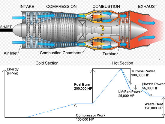
This is actually bad for the engine for all you guys wondering. One of the monitoring systems is to check for the exhaust gas temp because if the hot section of the engine gets too hot then it can bend and warp the turbine blades. Turbines rely on a cooling stream of air to protect the burner cans (where the ignition takes place) from getting too hot and burning holes in the cans and causing hot spots. this image shows what I'm talking about there would be a special inspection involved before the next flight which is a boroscope to check for internal damage.
http://www.comsol.com/support/knowledgebase/816/
This is all you need
1 Do General form PDE
2 Set dependent variables to y and v
3 set gamma to vx and yx
4 set source term to 0 and v
5 make sure da is 0s
6 Dirichlet BC at x=1 y=-1
7 Dirichlet BC at x=2 y=0
8 flux/source BC at x=1 set g = 0 for y and g=-1 for v
and the analytical and exact solution should overlap
Piezoelectric materials have a crystalline structure, that means that the orientation of the crystal when it was cut, during "poling", and the final orientation with regard to the electrodes will affect the voltage-strain relationship. The material properties will be different across different directions in the crystal. Here is some info: http://www.comsol.com/blogs/piezoelectric-materials-crystal-orientation-poling-direction/
To answer your question as best as I can: If you had a small cylinder of Barium Titanate (poled in the +Z direction), with a diameter of 1 in and a height of 1/4 in placed it on a plate with poling direction up, and pressed down on the top of the cylinder with about 5 lbf it would generate about 3V with with the positive terminal on the plate and the negative terminal where you are pressing (I hope that makes sense).
The EVGA GS 550w is a good PSU alternative. It uses a very similar platform, but is fully modular and even cheaper if relying on mail-in rebates.
> I assume this software uses only the CPU and is not GPU accelerated?
Maybe with the COMSOL suite there is a tool to do it but otherwise i really think you are going to struggle to come up with a way to MODEL fractal corrosion patterns while taking flow meandering and internal surface flow-pressure into account. http://www.comsol.com/corrosion-module
There's an article on using COMSOL to model penalty kicks here. That should help get you started at least. Of course, the relevant equations for the Magnus effect are on the wikipedia page.
COMSOL is a proprietary (and quite expensive) software, and if you don't have access to it, you could try ELMER which has many of the same abilities, and is free.
I did notice the radiator part too -- and for what it's worth, I don't recall ever seeing a black anodized heat sink in my shop -- but I decided that was kind of irrelevant to their overall criticism.
A lot of design work goes in to heat sink design. There's a fairly expensive commercial program, called Comsol, that does this among other things. For example: http://www.comsol.com/model/heat-sink-8574
I don't get the sense from this project that the developers have done any of the complex modeling of physics that's usually done to predict whether or not a novel heat sink design will work. If they've done actual experimentation to see how well it works, I can't find the numbers for that on their site, either.
Without experimental data or a reasonable model, I'd tend to agree with Hackaday that their copper foam heat sink more closely resembles an insulator.
Maybe these examples can point you in the right direction:
>The model performs a static analysis on a piezoelectric actuator based on the movement of a cantilever beam, using the Piezoelectric Devices predefined multiphysics interface. Inspired by work done by V. Piefort and A. Benjeddou, it models a sandwich beam using the shear mode of the piezoelectric material to deflect the tip.
And:
>The change of measured resistance under the longitudinal stress component is called longitudinal piezoresistivity. The relative change of measured resistance to the longitudinal strain is called the longitudinal gauge factor. On the other hand, the change of resistance under transverse strain components is called transverse piezoresistivity. The relative change of measured resistance to the transverse strain is called the transverse gauge factor.
Learn MatLab. If you can program in that then you should be able to pick up the rest.
The rest of it, I would ask in the lab. Basic fluid dynamics should be on khan academy.
Technology is still moving fast, however it's moving more towards efficiency than raw power, as we're focused on making technology more mobile.
As a side note, this is the reason that we don't see gigahertz climbing rapidly anymore.. http://www.comsol.com/blogs/havent-cpu-clock-speeds-increased-last-years/
They list a few cards here, but many are outdated, so only look at the newer ones. If you can, try to find exactly what the GPU is used for, as that will affect your purchasing decision.
The build might be older, but piledriver might be the only way to get large amounts of cores and ram for cheap enough.
I would look into
http://www.comsol.com/plasma-module
and then compare it with known simulations from propulsion (say, JPL or something)
Umm... no.
You are thinking of a crush test, not a bending test. Having the force closer to the edges (if the surface is uniform) would reduce the bend, not increase it, as more force is at less of an angle from its support point.
Which is why the weakest point of bridges is in the center, not the ends.
>If there was an inherent weak point, it would show up very obviously.
Not necessarily.
Again, you are thinking that the force load is even across the entire surface from a given load. It is not.
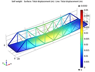
Look at this for a visual.
http://www.comsol.com/blogs/wp-content/uploads/2012/12/Truss-bridge-under-self-weight.jpg
You can clearly see that a point load excerpts varying forces across the distance. If there was an absolutely crazy defect on the outer margins, yes, it would fail there. But just a moderate weakpoint could still have a lower point failure tolerance than the center of the bridge, and you wouldn't see it bend there.
I don't really understand what you're trying to do... my guess is that you either want to use periodic boundary conditions, as /u/chaosbutters has mentioned or you want extrusion operators (discussed here: http://www.comsol.com/blogs/using-general-extrusion-coupling-operator-comsol-dynamic-probe/)
That's all I can give you without more information.
Yes you can do it in COMSOL, will it be simple? probably not. You won't find a package that will handle it automatically that I know of. I think you would start with the heat transfer add on package, create a time dependent study, then model the surface. You would then apply the radiation from the sun, IR form earth, and everything else, you can couple the different modes of heat transfer, and then run the simulation. I assume you have significant knowledge in the area of the simulation so you can tell if the results are realistic or not.
Also, COMSOL offers a bunch of free tutorials in major cities, you get a 2 week free trial of COMSOL with ALL the add on packages unlocked, and they usually have a very well versed engineer or scientist doing the demo so you may be able to get a more detailed explanation from them on how you could set up the simulation. This manual also has a few tutorials on how to set things up if you haven't seen it already:
http://www.comsol.com/shared/downloads/IntroductionToCOMSOLMultiphysics.pdf
Here is a link to the hands on demo's:
Instead of relying on badly written articles, you might be interested in the papers (by the said company)
- http://www.comsol.com/offers/conference2012papers/papers/file/id/13013/file/13649_allaei_paper.pdf
- http://sheerwind.com/wp-content/uploads/sheerwind/2012/10/Allaei-Andreopoulos_ASME-ES-FuelCell2013-18311.pdf
> The difference is INVELOX captures the wind kinetic energy and uses the pressure differentials to increase the kinetic energy available to a turbine and can do so in nearly any free stream areas with flow greater than 1 m/s. INVELOX passively converts the existing kinetic and pressure energy of wind to higher kinetic energy that can more effectively be converted to mechanical rotation of a turbine.
There is no magic there. Efficient (closed flow) turbine and low required wind speeds. How it works in practice is of course another thing and I wont be taking any stance on that. I assume if it worked well everyone had one already.
what type of computer are you running on if it takes 8 hours? This is a pretty standard exampleso i think youre setting something seriously wrong. Go look up this example
> Do we now look at closed systems when doing experiments, knowing all initial and boundary conditions?
That's exactly what we do! For physical experiments, it's an assumption, one that's seemed to hold pretty well. For intensively realistic simulations, it's baked into the rules: You very precisely define both the starting conditions, and the evolution of the boundary conditions over time; then you see what happens in the volume you're simulating.
How would you define a repeatable experiment when you can never create the same conditions twice; because "the conditions" refers to the state of the entire universe?
Whether we're built out of strings vibrating in higher dimensions, or just the interaction of quantum fields seems orthogonal to physicality in this sense. Perhaps when Comsol: String Theory Edition comes out it will let you set a starting hypervolume in more than 3 dimensions, and let you define boundary conditions as the vibrations coming in along a few hyperplanes through the strings. But that's still local effects.
As PeoriaJohnson already said MatLab can do this, and while I've not used anything else myself, a buddy of mine used Comsol to simulate EM-fields interacting with nano-structures in his masters thesis, and it seemed relatively easy to use.
The only thing I can say is, get a copy of COMSOL and play around with it and do your own simulations with the speed and size of a 747 hitting steel beams similar to those on the WTC. Everything else is just speculation... A copy of COMSOL runs around $10,000. But you may have better luck with mattys on the interwebs. Or sign up for a free class in your city from their website and you'll get a totally legal and free copy with a license that lasts a few weeks :)
EDIT: Just go here http://www.comsol.com/contact/ and give them your info. Just make up a company or something and request some more information regarding their software. They'll then start sending you email updates on free webinars and training in your city or one nearby.
If you need to do Multiphysics FEA simulation COMSOL Multiphysics can work with Solidworks, PRO/E, and Autodesk Inventor as well as import many 3D filetypes with its CAD Import module http://www.comsol.com/products/cad-import/ .