
What are
/r/ElectricalEngineering's
favorite Products & Services?
From 3.5 billion Reddit comments
The most popular Products mentioned in /r/ElectricalEngineering:


The most popular Services mentioned in /r/ElectricalEngineering:
Circuit JS
Autodesk Tinkercad
CircuitLab
Hackster
SlideShare
Digital
LTspice
SemanticScholar
Smallpdf
Banggood
Coursera
QUCS
Desmos
Library Genesis
gEDA Project
The most popular Android Apps mentioned in /r/ElectricalEngineering:

EveryCircuit

Flow Free

Graphing Calculator + Math

Physics Toolbox Sensor Suite
The most popular reviews in /r/ElectricalEngineering:
https://www.amazon.com/Electrical-Receptacle-Outlet-Ground-Tester/dp/B0012DHVQ0
Above is the answer. Also, do not consult this electrician again after:
> He also said that the the electricity has been "cleaned out" even before the house could use it so it's not possible that it's the grounding.
Depending on your current knowledge of course:
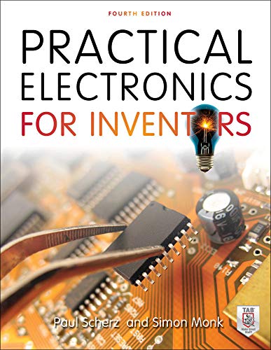
https://www.amazon.com/Practical-Electronics-Inventors-Third-Scherz/dp/0071771336
https://www.amazon.com/gp/aw/d/0521809266/ref=dp_ob_neva_mobile
These cover ALOT of material. I have practical electronics. It gives some of the physics which is nice. You'll get circuit analysis, transistors, amplifier, op amps pretty much anything covered in your circuits courses. It even gets into some digital topics as well. I recommend it!
Edit: let me know current you're knowledge of EE and I can recommend more.
I am a big fan of Electrical Machines, Drives and Power Systems by Theodore Wildi.
For me, this is one of the most well-rounded and applicable books on electrical engineering. The concepts in the book are well explained and the in-chapter examples are set up extremely well based on the previous paragraphs that lead up to each example.
It has a large chapter dedicated to synchronous generators and control, which is the type of machine used by most large power plants to generate power. I believe it also touches on the different types of basic power generation equipment and the basic heat cycle used in thermal power plants: energy to heat, heat to water, water to steam, steam to drive a turbine, turbine to drive the rotor of a generator.
It is also heavy on distribution and very in-depth on transformers. In my opinion, this is one of the best transformer and rotating machine books out there, period. It is usually the first book I reach for.
The Author (Make sure you click translate on that Wikipedia page) owned his own machine shop in Canada back when this type of technology was new (imagine that), the book was essentially his life's work and based on everything he discovered working with electrical machines which he also taught. He had 17 patents.
Source - I have read and worked through a very large number of electrical engineering books almost cover to cover.
There are some addons and tenplates to add components. But dont expect something like the typical sw for sch. I use it more for documenting porpuses and academic publication.
One example of an addon:
I think the hardcover books by John Markus are the most extensive collection I've ever seen. 1000 pages at 4-6 circuits per page. (amazon link)
Here is a presentation I found that has some good overviews on how GPUs function at a block level and also goes in depth on CUDA architechture, which is used in nVidia GPUs.
If you're not working on any insane projects, a USB oscilloscope might do fine, the lowest they go is $70 for a decent entry level 20mhz one (had this one for a year before I upgraded, it worked fine for me)
Disconnect, mark the switches that you are working with (LOTO), check for absence of voltage, ground and short circuit the equipment, and mark the area that you will be working at. This place explains it simply and has the simpsons! https://padlet.com/jmelsion/dsi5fut0w1jn
Hopefully this is ok - EETimes, one of the engineering websites I work with, is doing this giveaway of a Fluke 116 multimeter with a thermometer and carrying case (~$200 value, here it is on Amazon for reference https://www.amazon.com/Fluke-FLUKE-116-62-MAX-Kit/dp/B00DEF2G1Y). Enjoy!
Its a circular fluorescent. Those pop out of those clips. The bulb type is an FC8T9/CW on the smaller one. The wire connector is a 4 pin plug. fyi, the CW means cool white. you can go to a warm white(ww) for a nicer light.
here is the center one https://smile.amazon.com/Sunlite-FC8T9-WW-Fluorescent-Circline/dp/B009F90J7Q/ref=sr_1_2
​
they will probably delete this from the sub though since this isn't for house stuff.
This is a legendary playlist for me:
The same professor also wrote a book : Fundamentals of Microelectronics - Behzad Razavi
If you worked hard on your homework and paid attention in class and have a thorough understanding of the basics across the different subdisciplines of EE (power, microelectronics, and communications), then the FE is really easy. If you are an A-B student then it shouldn’t be a problem for you at all. You can buy practice tests on amazon. This is the exact practice test I took before taking the official test and it has pretty much everything that you can expect to see on the official test.
My advice, is to take the practice test as though you were taking the actual test (setting aside time to focus only on it in a quiet room), then use your results to see what you need to improve. Also become familiar with the FE reference handbook. They will give you a pdf version of the handbook to search through during the test, so familiarizing yourself with it will be beneficial.
I would recommend taking it now while you are fresh in college. $175 isn’t that much in the grand scheme of things, especially since it could potentially open up more opportunities (especially if you get your PE down the road).
That's it! The larger resistor means that when the inductor becomes conductive, the total current is U/R. If R is larger, the inductor doesn't have to store much energy to reach that current flow.
There is a geogebra worksheet that visualizes this:
https://www.amazon.com/Electrical-Engineering-101-Everything-Probably/dp/0123860016
Here is a book I recommend, starts from day 1 stuff, you can flip around where you need. There is free PDF online as well I think. Besides that, if you have the funds, I recommend asking your parents for an Arduino set and some come with project idea books and how to approach them. Other than that you can use codeacademy or other programming websites to teach you step by step.
Good luck!
It might be good to know that as a lifetime EE, you’re ALWAYS learning and trying to understand more. Get the book titled The Art of Electronics, 3rd Edition. https://www.amazon.com/dp/0521809266/ref=cm_sw_r_cp_api_i_R-8eFb73Z7TV8
Test the outlet, you can verify the wiring in any outlet with an inexpensive tester. https://www.amazon.com/Receptacle-Tester-Klein-Tools-RT210/dp/B01AKX8L0M
Shocks from the AC leakage from safety caps on improperly grounded supplies is fairly common.
I think (but am not sure) that a Speak and Spell may do this. If you scroll down through the Amazon listing attached, one of the Play modes pronounces each letter.
https://www.amazon.ca/Basic-Fun-Speak-Spell-Electronic/dp/B07PQT8DMB
Yes, a little bigger than a credit card, but still something she can carry around and has buttons large enough to know she's pressing the intended one and can see the letter clearly.
To make one yourself is quite possible, but in the interests of helping her asap, getting something premade might be a good idea. Then, once she has that, you can work on your own version with features you think are most useful to her.
You can do it two ways - if the 12V loads are very small compared to the rest of the system, you can connect a load (with a fuse, naturally), to the negative terminal of your battery bank, and a positive terminal halfway between the series banks to deliver 12V. The upside is that it is very simple. The downside is that if you have a lot of 12V loads you can unbalance the battery bank and accelerate wear.
The better way for larger loads would be to use a "24V to 12V stepdown converter". These are sometimes called "transformers" but that isn't correct - they aren't actually transformers. But they do step down to the voltage you want. You'd get one of the correct size for your loads, and connect it in parallel with your inverter to the battery bank negative and positive terminals. Here is an example of a 240W unit on Amazon (no specific endorsement, just an example from a search): https://www.amazon.com/Nextrox-Converter-Regulator-Step-Down/dp/B00BWKXTUU
It would also be possible to use a 120V -> 12V power supply connected to your inverter's AC output, but I wouldn't usually recommend that, since it is a lot less efficient (you have the DC:AC losses, then the AC:DC losses again). The only reason you might want to do that is if you have a complex control system, and are relying on the inverter to do coulomb counting and low voltage cutoff and whatnot. If you have a simpler system, no reason not to go right off the bank with a DC:DC converter.
Transmitting internet data over a phone line was how it worked for quite some time so it should be possible. I don't know how you'd implement it technology, as pointed out I assume you'd need a modem on both sides to interface with the phone line.
Would recommend to not measure the analog voltage over miles of phone line, due to (ohmic) losses and inaccurate measurement results. There's a StackOverflow post here with some more info about sending data over a phone line.
Check out https://www.tinkercad.com/circuits
You can run simulations using arduinos and other circuits without having to worry about overloading components. You can also mess around with coding the arduino and see other examples of pre made circuits.
You could run the Windows version of LTspice through Wine:
- Install Wine:
sudo apt-get install wine - Download and run LTspice for Windows.
Falstad's circuitjs is a super basic in-browser simulator with almost zero barrier to entry - but it's also quite easy to confuse.
LTSpice is a (free) rather better simulator with a horrendous UI - Windows exe, but works great in wine too.
The heart of many oscillator designs is an LC tank circuit which is an inductor in paralell with a capacitor. In a tank, one plate of the capacitor charges up to the supply voltage until the voltage over the capacitor equals the supply. Then, once disconnected, the capacitor begins to discharge into the inductor. The inductor however does not like a change in current flow so it begins to store energy in its magnetic field. Once the capacitor is fully discharged (and therefore not supplying current to the inductor) the inductor begins to compress its magnetic field to induce a flow of charge through it since it does not like a change in current. This then charges up the other plate of the capacitor until it is fully charged and then discharges the other way into the inductor thus creating oscillations.
This is the basics of how an oscillator works but in reality you must have some sort of feedback network to sustain oscillations due to losses. Typically the tank circuit will no longer be a single inductor and single capacitor but instead 2 caps and an inductor (Colpitts Oscillator), 2 inductors and one cap (Hartley Oscillator), 3 capacitors and one inductor (Clapp Oscillator), and many more varieties. The reason for these added components is to create a voltage divider and a means for a feedback path with a transistor amplifier.
Here is a simple JFET Colpitts oscillator. Here we can see that the feedback is along the tapped capacitor and the source resistor forces Vgs to 0 thus putting the JFET in the 'on' position. You could try building the circuit here as well.
I hope this helps, let me know if you have any other questions.
I think knowing some CAD package is almost required at this point. The form factor of the electronics is typically driven by the form factor of the actual product. Also, a lot of time you don't have the luxury of working with a mechanical engineer so you have to make your own case.
I find Solidworks pretty easy to use. The guys that invented Solidworks started a free online version called OnShape which is what I currently use for all my case design.
I think you would need a one of those larger battery packs that can handle that much power draw. Normal USB voltage is 5V and if requires an output of 10V maybe they will supply you with a different USB charger that's non standard.
Example of larger battery pack would be one that can handle 26800 mAH.
power output is 22.5W / USB A output.
Time 26800mah * 5V = approx 99 Whr, with usage you should have 3 to 4 uses per cycle.
No. Laptop will not run with that charger. Get a replacement charger so that you can charge up properly.
How much power are you talking? You can get a PC power supply that’ll do the job nicely. Or you can get a handy little converter like this one that can run off a battery or usb
Easy & expensive solution: portable power station.
Dangerous & cheaper solution: Disassemble the light, remove the AC regulator, measure the total LED string voltage (probably 80V+). Get a battery pack, connect to a 5W+ boost converter and drive the LEDs. Battery pack output voltage must be higher than the boost minimum input voltage.
Runtime in hours will be (battery pack energy Wh) * (90% efficiency) / (3W bulb rating).
Looks like Power Electronics: Devices Converters and Applications by Dr Chitode
I think cheap on demand mug printing companies have bots that plug in a dictionary list of every job into these mugs and spam them on Amazon
https://www.amazon.com/Switchboard-Operator-Mug-Coffee-Fathers/dp/B08Z359CG6
Search for a pwm motor driver.
Do not connect a motor directly to the Arduino pins: too much current and the inductive kickback will destroy the Arduino. You can however use Arduino to drive a transistor that drives the motor.
Sounds like microcontrollers would be a good place to start. Arduinos have a ton of educational material along with many standardized purpose specific daughterboards you could experiment with. Though, for a serious programmer, it may be a bit more 'training wheels' than you are looking for. Arduino presents a pseudo-C environment where you can expect most everything to have existing libraries and simple, high level functions calls to do all the low level microcontroller-y stuff.
If you are feeling more adventurous, something like a TI Tiva Launchpad might be more your speed. Paired with a textbook, you could get pretty deep into how you interact with on-chip peripherals.
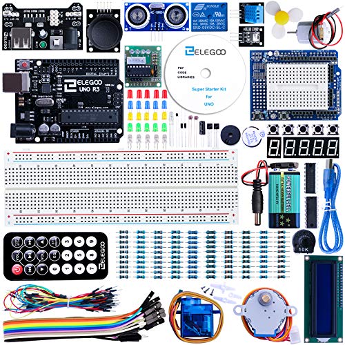
I believe it’s this one, super starter kit Project elegoo uno with tutorial for Arduino https://www.amazon.com/dp/B01D8KOZF4/ref=cm_sw_r_cp_api_glt_fabc_1LLcGbY96H00K?_encoding=UTF8&psc=1
Edit: my phone is in spanish
Buy an EMC book
Henry Otts book is very good
https://www.amazon.co.uk/Electromagnetic-Compatibility-Engineering-Henry-Ott/dp/0470189304
Tim Williams has a book that’s good if you design products
https://www.amazon.co.uk/EMC-Product-Designers-Tim-Williams/dp/0750681705
Electrical Engineering 101: Everything You Should Have Learned in School...but Probably Didn't By Darren Ashby. Excellent resource to brush up and tune-up your skills
number 2 and number 3 mostly; only one book on the list is a textbook from school: Muller+Kamins, and it has been useful again and again long after graduation.
I'm especially fond of the books on this list that helped me learn about something new-to-me, so that I could tackle an especially scary or difficult problem at my EE job, and successfully solve it.
And then there's (the best little $6 paperback book on Amazon) in which an advertising man from the 1950's, gives timeless advice which worked wonderfully for me in the 2010s, designing circuits. Don't read it until you've been a professional circuit designer for at least 3 years and/or two full design cycles; you won't appreciate its wisdom until you've personally experienced design-inspiration-starvation a few times.
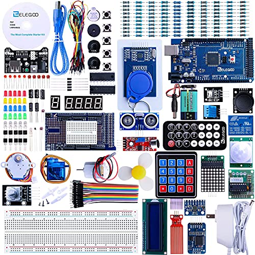
Obviously a lot of those kits are a huge marked up premium, but it does get you the basic parts to actually do things.
A while back I recommended this kit to someone, I didn't put a huge amount of resources into it though, and never had one myself.
https://www.amazon.com/Smraza-Ultimate-Ultrasonic-Mega2560-Projects/dp/B01L0ZL8N6/ref=pd_day0_21_4?_encoding=UTF8&pd_rd_i=B01L0ZL8N6&pd_rd_r=YKXVW5EZ2PZZ5K5V9J85&pd_rd_w=heGtI&pd_rd_wg=xi5mX&psc=1&refRID=YKXVW5EZ2PZZ5K5V9J85
Seems to have a lot of the basic stuff. What will happen is you'll want to do something, and the kit won't have enough of X to do it. So you spend $3 on amazon someplace and get 100x of something.
I'd also recommend getting a fast/accurate multimeter, a good quality wire cutter & bundles of wires. Next big upgrade would be getting a soldering station and probably an oscilloscope. There's a lot of good-enough working models on Ebay for $50-$100.
There are $20 DIY kits for a small oscilloscope, but honestly spending $50 more and getting an actual scientific device is probably better.
I also recommend this. There is a deal on Amazon right now for a really nice Arduino kit with lots of extra components and a lab manual with 35 experiments for $50. Regular price is $60 so you're only missing out on $10 savings if you miss the deal.
google tells me spirit halloween, amazon, homedepot, etc https://www.amazon.com/Spirit-Halloween-High-Voltage-Box-Animatronics/dp/B0711SRS6V
This is the one I ended up buying. Like I said earlier, it's a bit more pricey but it's well worth it. The way they present the material allows you to complete these projects in a reasonable time and learn something out of it.
But I did just look around and found it cheaper here
Best of luck to you!
If you check the pinout from the MAX232 chip to the RJ jack you might be able to use this cable.
I get plenty of relevant hits when I use Google to search for images of "stacked toroidal cores". Example. Clearly not only can this be done, it is done. What are you really trying to achieve though?
This is Georgia Techs 's High Performance Computer Architecture course. It explains from ground to top. https://www.udacity.com/course/high-performance-computer-architecture--ud007
Also you can find lecture videos of Dr. Onur Mutlu on YouTube. I didn't share a link for that because it updates often.
The sum of currents leaving a 'blub' is equal to zero, draw it in such a way so that you avoid the current I_5 for which you can't solve since there is no resistor between the two nodes.
Here is a detailed solution.
I would reccomend a Raspberry Pi
Not to hard to learn, and there is a lot of documentation about projects and you can actually build some really cool stuff. Only cost around $35
Loving your comments!
I've already started with some programming and have answered the first couple questions on Project Euler for practice (here's a link if you're not familiar: http://projecteuler.net/). I am writing codes in C++ and C. (I'm also not bad at basic but no one really counts programming in basic, cool to do on a calculator though). I do a minimal amount of html and very very little php for our schools newspaper website. Which I was tasked with both maintaining and pulling from dead a couple of times. So I'm excited about the programming side of things as well!
Piezoelectric materials have a crystalline structure, that means that the orientation of the crystal when it was cut, during "poling", and the final orientation with regard to the electrodes will affect the voltage-strain relationship. The material properties will be different across different directions in the crystal. Here is some info: http://www.comsol.com/blogs/piezoelectric-materials-crystal-orientation-poling-direction/
To answer your question as best as I can: If you had a small cylinder of Barium Titanate (poled in the +Z direction), with a diameter of 1 in and a height of 1/4 in placed it on a plate with poling direction up, and pressed down on the top of the cylinder with about 5 lbf it would generate about 3V with with the positive terminal on the plate and the negative terminal where you are pressing (I hope that makes sense).
These courses might be interesting for you:
https://ocw.mit.edu/courses/mechanical-engineering/2-737-mechatronics-fall-2014
Or this:
https://www.mooc-list.com/course/introduction-electronics-coursera
If you had more specific problems I might be able to help more. Personally though I wouldn't worry too much about feeling like you're "Just not getting it" or like the subject seems more difficult to grasp than others. Really it's something to expect out of all courses related to a specific engineering major.
The understanding you have, or will ever have, of most subjects is fairly surface level. Even if you've taken a full course in it. That's not an insult or anything, that's just how it works and that's what separates a specialty from everything else. You've no doubt learned a bit of chemistry but you couldn't design an arbitrary synthesis. You've learned a lot of math but you'd likely be fairly lost reading papers written by pure mathematicians. The gulf between learning enough of something to pass a class and talk about it, and understanding something well enough to approach nearly any problem is what you're pushing into right now. That is why classes like circuits can feel so unintuitive or difficult. You're getting the version of things without many of the simplifications and without glossing over the parts that get messy. Whether you were a CE learning about fugacity and steam tables, an ME working through theory of mechanisms and heat transfer, or an EE taking courses on circuits there's always going to be that sudden jump when the courses shift from teaching you enough to understand the basics of a subject to teaching you enough to really make a career out of it.
All I can suggest is do practice problems and play around a bit in simulators to get a more intuitive understanding. Here is one I often use when showing people on Reddit certain fundamentals. It's more of a toy though and you should really use something more sophisticated like SPICE for anything you actually intend to build. The visualization of it helps to see what's happening intuitively though.
The voltage generated by the probe is used to turn on the transistor, which acts as an amplifier for the signal. This way, the amplified signal can be measured more reliably than the probe voltage directly.
You can play with the circuit here: SparkFun_Soil_Moisture_Sensor. Changing the voltage of the upper DC source will change the simulated probe voltage. I have no idea what the full range of the probe voltage is, though.
~~I'm not an expert, but I don't think that circuit would work at all. Firstly, for a PNP transistor you need the base to be a certain voltage lower than the emitter so that current will flow, and in your circuit they look like they would always be too close.~~ Secondly, unless you introduce something like a potentiometer, you're not going to be able to change the amount of current there, it will just be what it is.
Edit: I just mocked it up in Falstad (http://www.falstad.com/circuit/) And it actually works. The key is that when the switch is closed, the two 100k resistors form a voltage divider. You can make that 900ohm resistor infinite or a short and it doesn't affect the 'on' state of the PNP (in the simulation). So the minimum I guess is what would be if that 900ohm resistor was removed entirely, so it would be V=iR, i =(13V-Vd(D1)-Vd(D2))/200k + transistor base current
I'm surprised at the responses so far. As someone studying engineering at one of {MIT, Caltech, Stanford}, I've found all three answers here to be pretty accurate:
There are many reasons why you might want to go to a "prestigious" engineering university over a lesser-known one, but I'm guessing you know most of them already so I won't elaborate here (although I'd be happy to if that isn't the case). Not to knock on NC State or any other school, but I'd just like to point out that going to a "name-brand" school often does, in fact, add value. Of course, this is ultimately determined on an individual basis; maybe it won't matter in your case.
The MDC01 is really nice.
$64 0-30 V 0-5 A 10mV resolution 1mA resolution 5mV constant voltage ripple 3mA constant current ripple
There’s also a 10A version (MDC02) but the the ripple/accuracy is slightly worse, still good overall though.
>I'm hunting for a Kurzweil SP5-8 power supply. Since it's not possible to get original one I read about specs on their website. It says: "External 15VDC 1.0A power supply". Which custom / universal power supply should I get?
Believe it or not... you should get an "external 15VDC 1.0A power supply". That is to say, you'll be looking for a "wall wart" type of power supply that outputs (at least) 1.0 amps at 15 volts DC. Assuming you're in the US, the input should be 110-120VAC; in Europe, you'd probably want one with a 220-240VAC input. On either continent, the 15VDC 1.0A output remains the same.
Next, you need to be concerned with the polarity of the output. Somewhere adjacent to the connection on your Kurzweil, you should see some markings similar to this:
+ ---(*--- - or - ---(*--- +
that will indicate the expected polarity of the center conductor and shell on the power supply.
This power supply (from Amazon) will supply 15VDC to a coaxial barrel connector (most common), with the positive connection on the center pin ( 2nd diagram above; most common). This particular unit is rated for up to 2.0A, so it'll handle the "up to 1.0A" that your Kurzweil is expecting.
In regards to safety with AC, the easiest way to make it safer would be to use a AC/DC power converter. These also usually step down the voltage as well, which also improves safety. A rough rule of thumb is that below 50 VDC is generally not dangerous to people. Something like this would work well.
To trip the voltage as you say, a relay module would work perfect for that. Solid state relays would last much longer if you are constantly tripping them but a standard relay would work wonders.
As for monitoring the current, you could do this many ways. A shunt resistor could work if you are ok loosing 1 volt or so. Or there are tons of Arduino ready current sensing modules ready for the picking.
3PCS 5A Range Current Sensor ACS712 Module AC/DC for Arduino (5A) https://www.amazon.com/dp/B08R5L45B2/ref=cm_sw_r_apan_glt_fabc_WVZGV8YG31M108YZPRA6?psc=1
SainSmart 16-Channel Relay Module https://www.amazon.com/dp/B0057OC66U/ref=cm_sw_r_apan_glt_fabc_7CA8Q0TR8348FX14XKEY
Power bank positive -> switch on the bottom -> reed switch COM -> reed switch N.O. -> LED strip positive -> LED strip negative -> Power bank negative.
Reed switch activates when there is a magnet nearby. You can install one half of it on the box and other half on the lid and make sure they line up when the lid is closed.
> the lights come on when the lid is down
You mean when the lid is up? Either way the reed switches linked above supports both: use NO or NC terminal.
Use a fish scale
If you really wanted to be analytical and had the equipment, you would use a tensile strength tester (google "Instron").
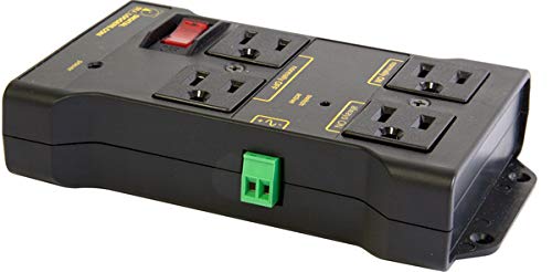
What country is this? If this is the US, then as long as the place is less than 60 years old or so you'll have breakers that will trip when there is too much current draw. If you don't feel safe, then I'd buy one of these: https://www.amazon.com/Electricity-Monitor-Voltage-Overload-Protection/dp/B07DPJ3RGB
It monitors your power usage in real-time so you can see the amperage drawn through the outlet. You can experiment and see for yourself what various loads draw.
You can install one of these current transformers over one of the supply wires of the lamp to generate the 'lamp on' signal.
Thanks for the advice, I think this put my on the right track! I have one of these pots and wired it up to the 3 available throttle wires. At first everything seemed to work perfectly, with the motor starting at about 10% and then slowly ramping up as I turned the dial. Then at about 90% turn (power seemed close to full throttle with the grip throttle) the motor abruptly loses power. Then as I turned it back it immediately jumped to full power at 90 and then slowed down as expected to 0.
I don't know much about pots but I thought I would see what happens when I swapped the outside wires (red and black, with white remaining on the middle post) and the behavior was the opposite with it jumping to fill power at 10% turn and throttling down until I got to 100%.
Assuming I've not done anything to damage the motor this is already much more usable for me, so thank you! But I'm also wondering why it's not using the full 100% speed range...
Ah yes, the age-old folly of attempting replicate RTL/TTL ICs on breadboard :).
I'm getting flashbacks of desk covered in components, jumper cables tangled up like spaghetti on my breadboard, up til sunrise many nights, and then it finally worked (or was it just a fluke? I'll never know).
I solved a lot of my resistor drama by getting a ton of potentiometers. If you're not familiar, it's essentially a knob that turns an electrical conductor along a strip of resistive material, effectively varying the resistance between the terminals. If you connect only the middle terminal and one of the outer terminals you have a variable resistor. They come in all different maximum values, and instead of guess-and-check, the process becomes adjust the variable resistor, check the resistance using a multimeter and then select your resistor (or just leave the potentiometer in place).
But if I'm being honest with you, I'd just grab a set of 74-series logic ICs. They typically have 4 basic logic gates per IC, and they eliminate a lot of the issues you'll have with RTL and TTL. Just look at the schematics on a typical logic IC. There are usually a ton of buffers, filters, etc just because of the sheer amount of "noise" and unpredictable switching that happens otherwise.
I've bought 5 of these kits and will probably buy many more.
Also, always tie your inputs to either positive rail or ground when not in use. I like to place a simple pull-up/pull-down resistor at each one, often accompanied by a SPDT push button. Floating inputs will behave erratically, usually resulting in a ton of unwanted toggling in my experience.
Best of luck, don't get too frustrated!!
Not really an EE solution... but have you looked at Heat Tape? Links is the first hit on Amazon, so you might want to look around more. But I imaging you could wrap it around the PVC, get it to the target temp, and bend away.
On a past project, we used heat tape to heat a long barrel of oil for extreme environment testing of some electronics. The tape was able to get the barrel hot enough that, when we weren't careful, we'd melted the electronics. That's much hotter than 225 F
I've bought an Eleegoo kit and I'm quite happy with it and playing arpund with it right now (this one: https://www.amazon.com/-/de/dp/B01CZTLHGE/ref=mp_s_a_1_8?dchild=1&keywords=elegoo+mega+2560+r3&qid=1617304854&sprefix=elegoo+Mega+&sr=8-8 ). It's affordable i'd say and comes with a lot of little modules (motors, temp sensor, joystick,...) to just play arpund and the documentation material available for download is decent enought to get started.
The 7400 series ICs are great for beginners. You might consider an assortment like this one Although I can’t speak for that kit myself.
You need a high voltage probe for your multimeter. It will give you a 1000:1 ratio. So your meter will read 20v if the probe is touching 20,000v. Here is an example. There are plenty more. Fluke 80K-40 High Voltage Probe https://www.amazon.com/dp/B000LDQ672
Building Electro-Optical Systems: Making It all Work https://www.amazon.com/dp/0470402296/ref=cm_sw_r_cp_api_fabc_SwGQFb9B50840
This one covers a bunch of stuff with frontends.
Horowitz and Hill have a solid section too.
The Art of Electronics https://www.amazon.com/dp/0521809266/ref=cm_sw_r_cp_api_fabc_FzGQFbJJ4PD2A
I think they're looking for a more economical way to achieve a similar thing and aren't saying that poor people couldn't figure it out.
I wish you luck.
Try something like this. ceramic heater plate
Here is a DC motor for sale on Amazon
It seems to need at least 1700 rpm. I would suggest contacting the seller to ask if it can run as a generator, and the efficiency.
I'm not sure of any websites but if you look up Professor Messer on youtube he streams a study group that you could follow along with. His channel is here:https://www.youtube.com/user/professormesser . You can buy the book from amazon for like 30 bucks I think. Good luck!
Arduino is a great tool to know. Even just using it to emulate more complex logic structures, generate timing signals, learning about communication protocols (I2C), etc. As for kits, there are all kinds. Many on amazon use the arduino as a backbone, like this one. Kits like that are nice, but it doesn’t come with any logic ICs for example. Im struggling to find a kit that even comes with op-amps, which are pretty significant devices. So, finding a true all-in-one lit like the old RadioShack kits might be difficult.
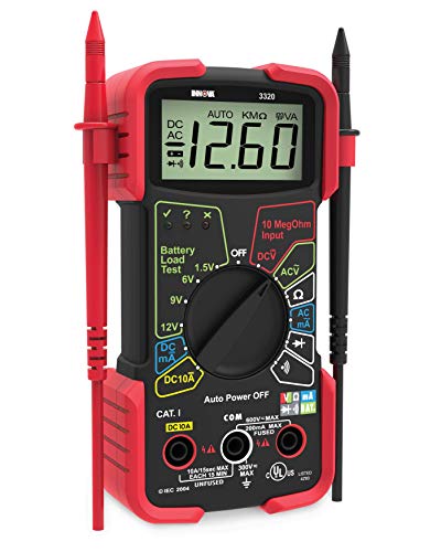
A multimeter is also a major tool to have for learning and building these circuits. I’d suggest the Tacklife DM07, if you don’t have a meter already that has uA/mA measurements.
i got a siglent on Amazon for around 450 CAD, looks like its only 350 CAD now, not sure if that qualifies as 'cheap'.
It should be standardized for JST PH connectors. A caveat -- We're making our best guess based on the photo and pitch, so there's a small chance that it's not JST PH but something looks very similar. Hopefully it's right.
There's one more thing to notice -- It actually take some practice to be able to consistently crimp the JST connectors. I strongly recommend you to watch tutorials (search on Google/YouTube) and practice with spare wires first. Since you ordered a connector set I think you can afford wasting some contacts to practice until you can consistently make a good one.
BTW, FYI there is an alternative -- You can buy something like this, cut all the 6 wires from the original cable, and splice it with solder and heat shrink tube. This is actually easier if you have experience soldering but never crimped JST connectors.
There's a book about an aspiring EE who grew up in Africa, built a wind powered generator and provided his village with electricity. It's highly inspirational.
It wouldn't be a bad starter scope. Rigol, Siglent and Keysight (more expensive) also make good ones.
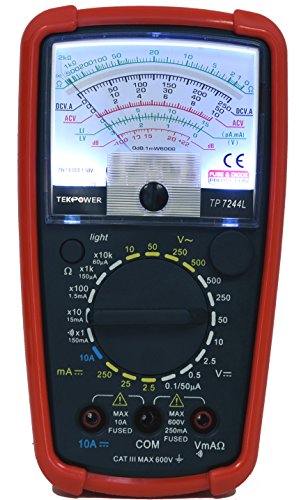
However, I'd likely wait a little on this and see if anyone at a radio club can provide him with a "gift" scope. Also, see if he starts seeing a need for a 'scope. They essentially allow one to look at voltages over time for circuits that have timing or analog waveforms. To start with, a multimeter would be a good thing to get as it would be used with simpler circuits and that's how he'll be starting out. Here's one that I bought. Also, he can actually put a multimeter together with this kit but I'd start out with the preassembled one just in case something goes wrong with the kit assembly (and he can use the other meter to debug it). The reason I'm recommending an analog vs. digital multimeter is they allow you so see relative changes in voltage or resistance vs. just flickering seven segment digits. A digital meter can be bought later. Some people will disagree with what I've said but "that's Reddit".
Sometimes people have older oscilloscopes lying around that they aren't using. Typically analog ones which would be larger, heavier but still useful. Just google (your area) "amateur radio club" and see what you come up with. It's likely they're meeting via a video link with all of the Covid stuff now.
It's up to you but the link you included is a good way to get started.
Some laptops such as dell also use a third wire for communication, telling the laptop what kind of charger is hooked up (ie 65w vs 96w).
If that isn't a problem you can get a high power converter such as https://www.amazon.com/dp/B08CTZ5F6N/ref=cm_sw_r_cp_apa_i_-i-tFbF548Q3Y
I used something similar to be able to power a gaming laptop from a cigarette lighter outlet without using an annoying, loud, and inefficient inverter. The dc-dc converter I used goes up to 10a and has an integrated heatsink. Totally silent and stays cool to the touch.
Ohhh. here you go
LED's https://smile.amazon.com/AIMELIAE-SFH485P-GAALAS-880NM-RADIAL/dp/B075FQ4C73/ref=sr_1_1
Resistors(use 2 in parallel for 5 ohm, it will run cooler with 1 watt dissipation) https://smile.amazon.com/Projects-10EP51210R0-Ohm-Resistors-Pack/dp/B0185FJZO8/ref=sr_1_5
LOL yeah that other thing would work great from 1000 feet away.
As u/Fuzzy_Chom already said they should be connected in parallel. The easiest and fastest way I can think of at the moment is that you use a power supply like this and a ready to use motor controller like this one. Those are probably not the exact parts you are looking for but just to give you an idea. For the power supply you need to make sure that it supports enough output current. The 8 motor will draw about 8.2Amps during startup. The voltage can be higher than the 4.2V you need for the motors since your are driving them with PWM but you should not drive the motors with more that 7 or 8V. This means if you have a 12V supply you should not turn the motor controller all the way up, to prevent any damage. So maybe it is best to stay at about twice the nominal voltage of the motor (8-9V output voltage of the supply) and you should be fine with any setting of your controller.
Embedded systems! Check out this book: https://www.amazon.com/Making-Embedded-Systems-Patterns-Software-ebook/dp/B005ZTO0LG?ref_=d6k_applink_bb_marketplace
The author also has a good podcast, and check our her website: https://embedded.fm/blog/ese101
You need some version of an ATS.
There's a zillion of them. Here's a place to startrandom automatic transfer switch off Amazon
Check this first: google your fan brand and check if they have an app or if the play store has a fan app you could use. For example Ceiling Fan Remote if you just want a controller.
If you want to make it yourself you'll need to do some research and have to know how to write android apps. It would be easier to make a little remote control yourself and program it with your Arduino for a project, no need to know how to make android apps.
If you want the app and create it yourself then good luck, find an oscilloscope first. Since you are in your first semester I assume you have acces to a lab or something. It will give you the best signal possible. Tear apart your controller, place the probe on the IR LED and a ground node and press the different buttons you want to use. The oscilloscope will probably give you a nice block wave of different '1's and '0's. Find a single bit, high or low, and define the frequency, with that you can define the whole signal, even if a double '1' is present. I expect the fan to have an on/off signal and higher/lower speed setting, nothing more. So It could be a 2-bits signal, could be 3-bits, but I don't think you'd expect a fancy protocol or something.
Then create the app, I have little to no experience in writing an android app, so good luck on that. Android Studio is your way to go I guess. Find tutorials to create a simple interface and how to use the IR led and combine those in a simple interface and use your found signals. creating an app is way different than programming a microcontroller. It's more java-ish than C, I expect you'd learn C in EE.
It's so easy. ;)
Good luck!
No problem. Most limit switches won't specify if they're normally open or closed, but if they have 3 contacts then 99% of the time you can configure them to be either. For example, these have both a normally open and a normally closed contact. However I wouldn't go for those ones specifically though because they're only 5A, I'd look for something closer to 10A.
I don't use a lot of reference material (outside of data sheets), but I do have the textbook from when I took circuits 1.
​
This is the newest version, I didnt use this version, I used the 4th edition, but It did a REASONABLE (not great) explanation of circuits, KVL, KCL, etc.
Oh yeah crap, totally forgot about that. You're not going to be able to find a 30A limit switch, so you'll have to use a suitably rated relay like this one, which is controlled by the limit switch. Connect the limit switch in series with the coil terminals and the motor in series with the power terminals.
The way I see it, the only reason to have a calculator instead of an app on your phone or a program on your computer is to use on a test. In particular, graphing is much better on a computer. My current favorite calculator app is Prime Calc, which I think is better then RealCalc, but there are lots of good ones these days.
On a computer Matlab or FreeMat. I use FreeMat a lot even though I have a Matlab license, just because it starts up quickly (unlike Matlab).
I don’t know the exact gauge of wire that it is (about 3mm in diameter), it’s just what is already there but it’s smaller in diameter than the wiring for the thermostats in other rooms. It’s just a plain old programmable thermostat for electric baseboard heaters, so honestly I’m stumped. It’s not a malfunctioning thermostat, it has worked on the other circuits. Must be a problem with the wire thickness (gauge), but have no idea why…
You can go to school, but I highly recommend the book Understanding Motor Controls. It's basically a textbook for school, but it has everything you would learn for much cheaper. You'd have to take it seriously and read at least the first half of the book. I'd recommend answering the questions at the end of each chapter to help further complete understanding of the topics. But if you read even half that book, you'd be able to read this schematic no problem.
Interesting idea!
So you’re basically going to parallel off the speaker from the smoke alarm, connect that to the trigger of the latching relay which will then cut power to your 3D printer incase of fire?
Without building a 9v to 5v converter using a voltage regulator, you could buy a ready made 9v to 5v usb converter from Amazon. 9v to 5v
This should work and make the whole project quite simple. Like the previous guy said, do test this since your speaker will have a source signal that fluctuates to create the beep beep beep beep, hopefully the converter will even it out to a stable 5V.
Now, just to add, you’re worried that your 3D printer will catch fire? Do you know what part of that printer you suspect will overheat?
If you do, you could use the same relay and create a thermal cutout switch that shuts it down when specified part goes above a certain temperature.
Only reason I suggest this is because if the device has already caught fire, it’ll short the circuit and trip the circuit breaker anyways? Better to prevent the fire in the first place…
Or you could go further and get a stepper motor connected to a fire extinguisher pointed directly at your device. This will be a bit more complicated but it will be the first line of defence against a full on fire.
If it can only be operated in parallel and not both parallel and series then the calculations become much harder.
You might be better off getting something like this.
You either need a flasher designed for LEDs (not all motorcycles can use them) or there are plenty of off-the-shelf LED resistors designed for exactly this. You can get them cheap off Amazon, or your local auto parts store (Autozone, etc) will carry them.
I found some on amazon for less than $100. No promises on quality e.g. if safety or reliability is required I would spend the money and go with Fluke. Here is one for $70
https://www.amazon.com/dp/B06W2KFZLW/?ref_=cm_wl_huc_item
If all you need to do is measure AC and it does not have to be clamp on here is an inexpensive option.
I would look into SDRs and radio and work to get your amateur radio license. Getting licensed is a good way to learn a lot about basic circuits and a good way to pick up some scholarships along the way.
I would start with a RTL-SDR. A full kit is about a $40 investment. https://www.amazon.com/gp/product/B011HVUEME/ref=as\_li\_tl?ie=UTF8&camp=1789&creative=9325&creativeASIN=B011HVUEME&linkCode=as2&tag=rsv0f-20&linkId=b3bd3c48a6a7e921144609cb59359f0e
I recently finished building this kit, and was surprised by the thoroughness of the instructions and theory presented in the manual. Even if it's not the exact thing you're looking for, it's a good design reference. https://www.amazon.com/Elenco-Radio-Kit-Combines-Transistors/dp/B008515U1U
To answer your first question, AM and FM receivers are fundamentally different in how the audio is demodulated. AM is far simpler in that just a peak detector, via a diode, can work. The audio is modulating the higher frequency carrier's amplitude. In FM, the instantaneous frequency of the audio modulates the frequency of the carrier. A simple FM demodulator in software consists of a phase differentiator. It's a little more complicated in the analog world.
Well, there’s plenty of oscilloscopes out there with a bandwidth up to 100MHz you can get with $200 like this. If you’re just wanting to look at the charging and discharging behaviors of inductors and capacitors, an even lesser oscilloscope would be needed. I have a Digilent Electronics Explorer board and it has almost everything you might need in an EE lab setting (oscilloscope, waveform generator, logic analyzer, power supply). It’s the older one though, the new one is this.
So my guesses on the 5 conductors:
Left and Right: Obviously Left & Right Positive
Ground: Is this ground for both??? If so, I will splice both grounds together then put the combined into my connector
Shield: I know what a shield is.... I don't know what I would do here though. Maybe this was a shield of the old Aux port? This is what the old aux port looks like
Blue cable: I have no idea other than I know on the car stereo there is a single button for CD and aux. If the aux is not connected, it will play the CD when the button is pushed (also when you pull out the aux it defaults to the Aux... I'm wondering if this is a check circuit to see if the circuit is complete to know if switch to aux from cd. If so... what would I do? Put a switch in between?
Thats where I'm at now