
What are
/r/ArduinoProjects'
favorite Products & Services?
From 3.5 billion Reddit comments
The most popular Products mentioned in /r/ArduinoProjects:


The most popular Services mentioned in /r/ArduinoProjects:
Hackster
Autodesk Tinkercad
elasticsearch
Filemail
Circuit JS
Resolume Avenue
Kerberos.IO
ImgBB
balenaEtcher
Mycroft
Weather Underground
IFTTT
ThingSpeak
Visual Studio Code
The most popular reviews in /r/ArduinoProjects:
If interested, there is also a project tutorial including code files and instructions:
I did something like this a while ago using openhardwaremonitor to do the legwork of reading the CPU stats and a small C# application to send it to the arduino over the Serial interface.
It was a while ago so I don’t have any details saved, but this is an example: https://www.hackster.io/zakrzu/arduino-pc-monitor-66c07a
RS232 to TTL Converter, possibly with a gender changer adapter. Get the serial communication rates and protocol from the scale manufacturer and write code for it, or if you're real lucky find an Arduino library that can decode the scale output.
If interested, there is also a project tutorial, including code files, Gerber files, and instructions:
https://www.hackster.io/kutluhan-aktar/jigglypuff-iot-carbon-dioxide-and-dust-monitor-w-telegram-7ba64b
​
Link for the updated article. Please leave your feedback and projects if you would like to share them in the article. I will be happy to curate.
An Arduino doesn't have the memory or processing power for voice recognition. The Mycroft software is pretty much the de facto standard for DIY voice recognition systems and will run on a Raspberry Pi 3 B or above. It's overkill for your requirement but there aren't many options for DIY voice recognition.
An easier version of the raspberry pi idea would be to use a pi zero flashed with kerberos.io or motioneyeOS. They have built in functions for motion detection and can trigger an alarm when motion is detected.
Sort of. It basically provides a web enabled interface to the device. The logic for the circuit is still written to the device (via arduino IDE in my case) and assumes there is some expected input or output from one or more pins. In my example, my widget has three buttons for each LED. When I press the buttons on my phone, the http request is sent from Blynk's server (I'm guessing) to my device and sets the pin's voltage high or low.
With your rfid reader instructable, the ardunio is acting as a keyboard and is typing the password if the correct card id is detected. Running through some basic arduino tutorials will be a great help to learning how the code & arduino works.
It looks like there is a finger print scanner and a library available for the arduino, you can skip the parts involving the lcd screen.
To use the laptops camera for facial recognition, it's easier to use software that will unlock your computer, or at least software that will run in the background and tell the arduino to proceed. The ardunio itself isn't powerful enough to process images if you used a webcam anyway, and it has no way of accessing the laptops camera if it did.
If you're looking for other options, maybe a keypad you have to type in the right code, or an IR receiver which you have to point a remote control at?
Depends. I'm running this display on Rev2 Uno (and this looks like a Rev3 board, based on the color, not that I'm an expert).
And I run it with USB 2 only. So that has to be less than 500mA in total and it runs fine, even for longer periods.
I think the regulator itself is an ams1115 (5V, 1A).
If you're running it from USB only, you're probably going to pull more than USB can handle (and then the port shuts down), before your max out the regulator.
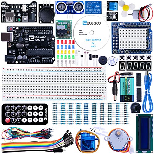
I started with a kit like this.
I really liked it. Ended up making something to turn on LED lights in the bathroom based on movement and fade out after an amount of time with no movement. Very fun to mess around with.
5 pack wired with probes on both ends $10
10 pack of probes unwired $7
These probably aren’t the best priced but they’re examples of what you’re talking about.
I used the OLED screen from amazon - Link to Product But a lcd monitor should be even easier to hookup imo. You can same-day ship things from Amazon depending on where you live.
Can you upload a picture of your wiring? I'll take a look
Ok, in this case I recommend getting some basics down first (I started there myself, though I had decent understanding of electronics and wrote code in a bunch of different interpreted languages before I got my hands on Arduino). Going back to basics was pretty beneficial.
Vilros makes a pretty decent starter kit you could get on Amazon. It has everything to get you started and step-by-step manual that comes with it is pretty damn good. The kit has all kinds of components you could re-use for your future projects, comes with an Arduino Uno, breadboard, jumper wires and a bunch of other neat things. Super straight forward, easy to understand and very very informative.
Totally worth the money in my opinion
https://www.amazon.com/Arduino-Ultimate-Starter-Circuit-Learning/dp/B00BT0NDB8
https://i.imgur.com/3juLrn2.jpg
Yup, same hat I got in a Mega 2560 Project box from Elegoo. If you did a little research I'm sure you'd find the actual part on aliexpress or something for 50 cents.
Edit: Felt like a dick for not being more helpful. Everything he used is in this kit (https://www.amazon.com/UNIROI-Mega2560-Tutorials-Complete-Resistance/dp/B07BGVVJJN/ref=sr_1_3?dchild=1&keywords=mega+2560+hat+prototype&qid=1594764130&s=electronics&sr=1-3). That might help you track down the hat if you need it.
Edit2: Lol, it literally says "Arduino MEGA Prototype Shield v3" on it. I guess we all missed it. I found some knockoffs on aliexpress for 2 bucks (with shipping), little more for real ones (I'm using the RoHS mark be my "real" marker).
Great idea... we do sometimes forget that we have incredible sensory and control devices sitting in our pockets all the time!
Link: https://play.google.com/store/apps/details?id=io.dabbleapp
Love the idea of the datalogger.
Please take a look at AppInventor tutorial for this App. All the information of how to make this App is available there. If you didn't want to make this yourself, you may also download it from Google Play Store.
​
Thank you,
Stonez56
​
Good job. If you want to take your project to the "next step", I would recommend replacing the photo resistor with an I2C light sensor. There are several devices/boards available.
Google "i2C light sensor". An example would be:
https://www.amazon.com/Adafruit-4162-VEML7700-Lux-Sensor/dp/B07S9TD2W1
These devices would provide an actual light level value that scales to the current ambient level, allowing you to read lux in a rather dark room to very bright, such as direct sunlight.
May be you can monitor your plants sensor data using this application https://play.google.com/store/apps/details?id=dev.najad.iotplantmonitor . The application uses websocket to connect to the microcontrollers like ESP32 or ESP8266 and can display the moisture sensor value, temperature, humidity, pH in the app dashboard.
You can check this example project https://diyusthad.com/2022/11/iot-plant-monitor-using-xiao-esp32-flutter-app.html
Need more details.
There are two parts of this type of project.
How to mount the LEDs and how to control the LEDs.
If you are using the WS2812B strips, measure the total length of the strips you would like to use.
https://www.amazon.com/150pixels-Individually-Addressable-silicone-Waterproof/dp/B01DLSUHWS
Here is a 16 ft strip, 150 LEDs.
Each LED requires 3 bytes of RAM, so 150 LEDs require 450 bytes of RAM.
The Arduino UNO has 2048 byte of RAM in the chip. So 1/4 of the RAM is used up.
If you use two of these strips or 300 LEDs, that's 900 bytes of RAM or 1/2 the total.
The software that needs to be loaded on to the Arduino to control the LEDs also needs some RAM for its own.
From these numbers, calculate the total number of bytes needed.
How you are going to mount these under your car so that they are safe and protected from water and dirt is up to you.
Good Luck, Have Fun, Learn Something NEW
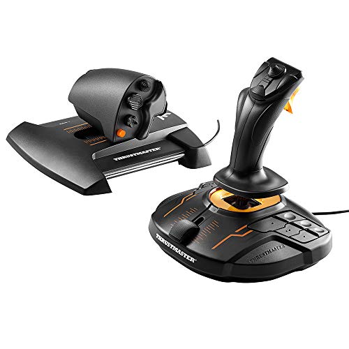
i actually bought the disc and the controller together, either Amazon or the company
All modern solder has flux inside. When you get better, that will be enough for simple soldering jobs, but for finer you still need external one.
As far as flux goes i always have pen flux for simple tasks (its so easy to apply) and gel type for finer pitched (harder to solder) parts.
The current pen i use is this https://uk.farnell.com/chemtronics/cw8100/dispensing-pen-flux-no-clean-9g/dp/130692 . Its great.
As for paste I have absolutely no idea what I had in the office. https://www.youtube.com/watch?v=iKDAmY9Rdag&ab\_channel=SDGElectronics this could be a good starting point to find one. From the once you've send, the first one will probably better but I have no idea. I tend to stay away from completely liquid fluxes, unless I need something specific.
Spend $12 on a premade dispenser that you can motorize.
Yea, I was suprised too.
Sensor is the TTP223B .
I used this AMP and this BT receiver To be honest you don't really need an Arduino, I used one so I could do other fun stuff down the road. Basically you wire the buttons on the receiver board to whatever buttons you want to use on the old radio.
Thanks - yes from a funktional perspective this is exactly what i need.
But i would prefere it to be fully packaged into something like this:
​
I'm not really sure what the idea was, it kinda faded away. re: the belt only moves on one direction
I had another 'bright idea', what if you used toy car motors that are 3v, attach that to the worm axle.
The problem is that the card only rotates 90 degrees at a time, but how do you ensure 90, instead of 87, or 103 or 180?
Here is an example of the motors I'm talking about. Cost is USD $11 for 12 motors.
https://www.amazon.com/Topoox-15000RPM-Electric-Science-Projects/dp/B07JYM8H18/
> Like, if I had a way to switch directions on the worm-bit without having to change the direction of the motor, that would be the a perfect solution because I wouldn't need to do one "stitch" it in two steps, making the whole thing that much more efficient.
Can you explain that idea?
He’s trying to sus out how the windows based program gets the info from your CAD system.
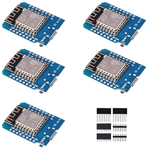
One suggestion I have would be to use the ESP 8266 or ESP 12. You can get a 5 pack of the 12’s off Amazon for $16 https://smile.amazon.com/dp/B081PX9YFV/ this module has wifi built in.
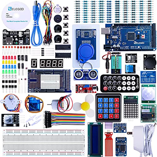
This is the kit I bought 2 years ago to start, and then got lost in learning. I wish I had the time to sit down and learn but with family and work, I just don’t. I would love for someone to guide me in the right direction. If this kit won’t work or help, let me know, I’ll get the right stuff or any additional needs.
ELEGOO Mega R3 Project The Most Complete Ultimate Starter Kit w/ TUTORIAL Compatible with Arduino IDE https://www.amazon.com/dp/B01EWNUUUA/ref=cm_sw_r_cp_api_i_AVP8J61FZGMAJFESBN8V?_encoding=UTF8&psc=1
waveshare 1.5inch RGB OLED Display Module, 128x128 Pixels Displaying 65K Colors, Compatible with Raspberry Pi Arduino STM32, SPI Interface https://www.amazon.com/dp/B07DBXMFSN/ref=cm_sw_r_cp_api_i_YDE73K47516YD4B0CTY6?_encoding=UTF8&psc=1
Amazon link, but I’m sure you could find it cheaper elsewhere!
Get a servo driver board...something like this - HiLetgo PCA9685 16 Channel 12-Bit PWM Servo Motor Driver IIC Module for Arduino Robot https://www.amazon.com/dp/B01D1D0CX2/ref=cm_sw_r_apan_i_2460M2HWQF526ZN3A2H9?_encoding=UTF8&psc=1
And power it separately from the Arduino.
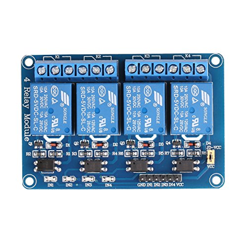
Yes, the microcontroller would just need to operate the switch in parallel. This would be done most likely with a relay or just a transistor.
Probably would want to use an esp device as it could have built in WiFi and would still program through the ide.
The real question is security. Do you want your shock collar open to the internet without things like encryption and authintication? Probably not...
So I would think I'd do an old laptop with a vpn server. (OpenVPN etc.) Then have a USB relay you can activate after logging into the laptop.
SparkFun Qwiic MicroPressure Sensor - Miniature Breakout - 25psi piezoresistive Silicon Pressure Sensor - Calibrated & Compensated Pressure Sensing Range of 60mbar to 2.5bar - Ultra Low-Power https://www.amazon.com/dp/B08DG8Q18H/ref=cm_sw_r_apan_i_PHPP4ZEYWZSQP6P3XRRM?_encoding=UTF8&psc=1
I use a bunch of these in differential pressure applications kinda like what you're talking about. I2C communication and the qwiic libraries make it really easy.
Official Creality Ender 3 Pro 3D Printer with Removable Build Surface Plate and UL Certified Meanwell Power Supply, FDM 3D Printers for DIY Home and School Printing Size 8.66x8.66x9.84in https://www.amazon.com/dp/B07GYRQVYV/ref=cm_sw_r_cp_api_i_HBDWXCD3N319PF424SHY
https://amazon.com/gp/product/B079NXDYN7/ref=ppx_yo_dt_b_search_asin_title
Doesn't show much more than what I've posted, but I don't mind pulling one apart if I can find a spare. I don't expect that the IC could be reprogrammed, but what about removing the matrix and connecting it in some way to an arduino Uno..?
I bought this Arduino starter kit on Amazon. I can't wait to get it to start working on a impact sensor system.
There is a 12V light bulb that could make it just perfect :)
If you are completely new i recommend starting with something like this:
https://www.amazon.com/ELEGOO-Tracking-Ultrasonic-Intelligent-Educational/dp/B07KPZ8RSZ
You don't need to worry about the construction design and it already runs code. From there you can start amending the code, tinkering with the hardware and so on. If after 1month you still like it you can start an own project.
The robot from your link has multiple high thresholds: cost, 3d printing infrastructure, soltering, knowledge in hardware and software. But you can learn all this within some months, I just recommend an easier start 👍
I used this pump/vacuum and air valve: materials Yes agree, I’m not sure how to monitor the air coming in and out 😅 I’m new to electronics so not too sure how to accomplish that. Yes I was thinking of coding it so that one tap means inflate and two taps hold still and three taps means deflate. Do you have any ideas on how to do that? For the pulse sensor I am using this one touch sensor
This is the one I used. It has the same layout as my small punch board.
https://www.amazon.com/dp/B08BWPGSSC?psc=1&ref=ppx_yo2_dt_b_product_details
Make sure this is what you want. It is built just like a punch board where the holes are all bridged like the punch board is. But for me it made it so darn easy to move my project from punch board to a permanent board.
If interested, there is also a project tutorial, including code files, Gerber files, and instructions:
https://www.hackster.io/kutluhan-aktar/iron-man-walkie-talkie-two-way-radio-for-texting-w-lora-8da393
Thanks! It came in an assortment pack. Here's the link to that:
Neat! Recycling is always great, and PET certainly has a lot of uses. Very cool. Would be awesome to see the completed project. But yeah, a mosfet should be plenty to power a hotend. You would need to make sure to monitor the temperature though, you don't want to keep the hotend constantly on. Never considered powering a hotend as a standalone unit... Perhaps look into DIY filament extruder, there are plenty of tutorials online. As for stepper - just get a standalone board, something like this one. They are really easy to implement. Feel free to PM or tag me or whatever, really interested in seeing this project come to fruition. I also have a small arduino oriented discord server, can send you an invite if you feel like joining.
https://i.imgur.com/wSC3ySF.jpg
Here you go! Here’s an Amazon link to a small terminal block too. Blue Sea Systems Terminal Blocks 20A - 65A https://www.amazon.com/dp/B0000AZ6Y3/ref=cm_sw_r_cp_api_glt_i_ADR9PFFBS66PA58N4REJ?psc=1
Oh and happy cake day!
The pro micro (at least the knockoff ones I've gotten) are particularly brutal about this. I have nanos, unos, and 8266 boards all over the place and have never had this happen. But like you, I had a micro port snap off just from the normal wear and tear of mounting the board the other day.
consider other boards when you don't need features specific to the pro micro. I use nanos when I don't need the micro's particular USB magic.
try to only have the cable connected when the board is in a stable place. The cord acts like a lever.
similar to what crispy's doing, I have a pack of usb B breakouts in the mail. By using these as the connection point and keeping slack in the wire between the breakout and the original micro port, I'll have a more durable target to take the hit on mechanically stressful plug/unplugs. You may also be able to connect these to the existing pins when a port breaks off, saving the board from the garbage.
long term, recognize that this won't improve until it hurts company's bottom lines: post broken photos (way more powerful than text) to amazon with a comment specifically indicating that the board needs a redesign in this regard, because it's a design flaw, not a QA flaw. (r/ULPT edition: take many sets of photos on different surfaces and trickle these in over the next few months).
Just to confirm, do you mean something like this
Just to confirm, do you mean something like this
Very new to all this, so my bad is this is a very generic and useless answer. It's an LCD1602? Don't think this is the answer you're looking for but I don't see any other identifying marks. If it helps, this is the kit that came in.
https://www.amazon.com/dp/B01ITBIYJK?ref=exp\_learnelectronics\_dp\_vv\_d
Here are some questions to answer to help you pick a power supply:
- Do you just want to power your stepper driver board with a bench top power supply? Search 12V desktop power supply.
- How much max current do your stepper motors (and driver board) draw? Buy/Create a power supply based on the total max current needed at 12V.
- Are you running from a battery? Maybe you need a DCDC step up or step down power supply that converts your battery voltage to 12V regulate for your stepper motor driver(s).
Say you have (4) stepper motors driven by a L298 driver board and each L298 can drive 3-amps peak (2A continuous) then you need 4*3 = 12 amps at 12V or at 12*12 = 144 watt 12V DC power supply. For example this if you don't want something expensive. Or this if you want something more useful for future projects. Note that this sizes the max current for 24 Watt steppers. Most stepper applications will not sue the full drive force of the stepper so you can get away with smaller power supply in that case.
Good luck.
I have one of these too. Works quite well. Not 3D cause it is one flat screen view though. Nothing really compares to a binocular dissection microscope.
Wolfwhoop WT03 Micro FPV AIO... https://www.amazon.ca/dp/B06XB2ZRBP?ref=ppx_pop_mob_ap_share
This transmits video. All you have to do is hook it up to a lipo battery. They get pretty hot so you may want to add a heat sink. On a quad the air cooling makes a heat sink unneeded. And never turn it on without an antenna attached. It will fry itself. If you use a separate battery just for the camera you will get cleaner video than if you tap into the one with the motors and all that. You will also need a receiver.
I have these and they work quite well.
https://www.getfpv.com/eachine-ev800d-5-8g-40ch-diversity-fpv-goggles-with-dvr.html
And the front comes off the headgear if you just want to use it as a monitor. As for doing it with Arduino I wouldn't bother. The transmitter is far superior, very powerful and only $20. But I do love Arduino don't get me wrong.
This is a bit of a stretch but I tried to use the tinercad equivalent of this for some basic circuits, but it didn't have enough options as to what parts you could pull into your simulation. Could you add stuff like these rf transmitter/receivers?
Well, I'd say that if you want to do that from Linux you can just use balenaEtcher or if you need to flash a Windows ISO, you can use WoeUSB (no GUI though). But Etcher is fast and reliable for any kind of ISO.
If interested, there is also a project tutorial, including code files, Gerber files, and instructions:
https://www.hackster.io/kutluhan-aktar/iot-heart-rate-bpm-monitor-and-tracker-w-tuya-smart-3f8826
Use transistor as switch inter (gnd of fan) and (gnd of batterys). In the base of de transistor use a resistor to limit current. Cosidering hfe of transistor you need minimun a current 100 less in the base. https://www.hackster.io/task-arduino/how-to-drive-dc-motor-with-arduino-b35d26
If interested, there is also a project tutorial, including code files, instructions, and the Android application:
For example, you can get a gas sensor module that can you can hook up directly to an Arduino. You can display the results from the air on a 16X2 LCD display. Then if you want to make the project more complex you can display the results through the web with a WiFi module.
There are tons of examples on the internet. For example:
https://www.hackster.io/TechnicalEngineer/arduino-based-air-quality-monitoring-iot-project-7f3d14
Are you using the piezo as a motion sensor? I'm working on the same project using a potentiometer.
You can't, you need to use some type of digitally controlled switch, typically either a transistor or a relay. An N-channel MOSFET (transistor) switching your load to ground would be the typical solution in this case.
Someone used the same display in a game.
https://old.reddit.com/r/arduino/comments/hk2g4g/reaction_timer_game_with_4digit_7segment_display/
.
More code? More info?
https://www.hackster.io/mike-mcroberts/reaction-timer-game-with-4-digit-7-segment-display-db77dd
It's built with fischertechnik, a construction toy originating from Germany. See full describtion on Hackster: https://www.hackster.io/ArduinoFT/pick-and-place-delta-robot-controlled-by-arduino-mega-3eff40
There are many examples out there, but one simple way to do it: Connect a pin or relay to the back side of the lock/unlock button(s) inside your car, and put an RFID-reader in the little triangle in front of your driver's mirror.
Then program an Arduino to trip the relay for half a second every time a known chip is registered by the reader.
Here are two of the setups I 'stole' from for my project:
https://www.hackster.io/team-familab/start-your-anything-with-nfc-766c10
http://www.webnology.ch/en/arduino-rfid-access-control-eeprom.html
Sound Sensor Module Sound Detection for Arduino
reference link below
Agree try and watch some "how to solder" videos on youtube. If you don't have a good solder iron and you plan to work on electrical designs in the future it's worth the investment. You can get a good one for low cost. This one is $18. When you're ready to go pro or want to buy good gear get this one next.
I have nanos for my projects. the original ones I just used the header connectors to solder wires to so I can remove them fro the nanos. The latest project, I used these adapter shields so I can screw the wires in place. I used a small plastic box to hold it, 12v to 5v converter and a 3s lipo pack for power. Currently running 100 pixels.
Also, you can use a portable USB charger for power, no need to regulate it down.
https://www.amazon.com/HiLetgo-Lithium-Battery-Charging-Protect/dp/B00LTQU2RK/ref=sr_1_1_sspa
I am currently using these, and they supply power to the load and charge just fine.
not so simple.
most encoders on amazon look like this - https://www.amazon.com/Cylewet-Encoder-15×16-5-Arduino-CYT1062/dp/B06XQTHDRR/
while it functions the same it is different.
Is this one good? There’s 4. I want to wirelessly connect them. https://www.amazon.com/SongHe-Development-Dual-Mode-Bluetooth-Antenna/dp/B08246MCL5/ref=mp_s_a_1_1_sspa?dchild=1&keywords=esp32&qid=1630834058&sr=8-1-spons&psc=1&spLa=ZW5jcnlwdGVkUXVhbGlmaWVyPUEyUTM0VlRUQ1RIRFI4JmVuY3J5cHRlZElk...
just nichrome wire.. i have a relay board that's driving this direct from the battery -- https://www.amazon.com/SainSmart-101-70-103-16-Channel-Relay-Module/dp/B0057OC66U/ref=sr\_1\_5?dchild=1&keywords=arduino+relay&qid=1629677563&sr=8-5
Do all the motors need to have speed and direction control ?
Can some motors be single direction with speed control ?
https://www.amazon.com/HiLetgo-PCA9685-Channel-12-Bit-Arduino/dp/B07BRS249H/
I found the board on amazon, listing is a bit weird considering my board says 350x but it looks the same as the tan 1310/1510 version. Take a look maybe youll see something i dont onehttps://www.amazon.com/dp/B089ZSRYCX/ref=cm_sw_r_cp_apa_glt_fabc_F03VYCKP23WW9QMJBHYS?psc=1
learn how to read light, what light sensor, learn how to control led brightness.
I used this kind of sensor https://www.amazon.com/eBoot-Photoresistor-Sensitive-Resistor-Dependent/dp/B01N7V536K/ref=sr_1_2?dchild=1&keywords=Arduino+Light+Sensor&qid=1615764374&sr=8-2
the resistance varies with lightness!
It’s possible, I find this Bluefruit but, before I spend money, again, on this project... I try to find a solution with what I have.
Adafruit Bluefruit LE UART Friend - Bluetooth Low Energy (BLE) [ADA2479] https://www.amazon.ca/dp/B01BMRD76S/ref=cm_sw_r_cp_api_i_DCV7PB0YBQJJ04AYG1MR?_encoding=UTF8&psc=1
IDK if this is what you had in mind or not, but I got one like this. The actual one I got was the higher amp and was 12V to trigger. It was a real struggle to figure out how to wire it as it came as a board with no paper work and there doesn't seem to be a real standard for these things so no .PDF online.
I THINK I got it figured out and it is triggering using the Arduino. I use it to control fluid transfer pumps that are 12V 10A (I got the heavy duty version).
They basically do whatever you want. NO, NC, switch high or low, etc...
IF you need FAST switching, you should find another solution, these are mechanical. I wanted another option for an EFI controller for a car. They have to switch VERY fast.
CHECK THE SPECS BEFORE YOU ORDER
I’m most likely going to use these
Gikfun 1V-6V Type 130 Miniature DC Toy Motors for Arduino Hobby Projects Diy (Case pack of 6) EK1450 https://www.amazon.com/dp/B07SQXRSNR/ref=cm_sw_r_cp_api_glc_fabc_eMk2FbBCGTHC8
Quick Note:
If you just want to control a very short LED Strip this way you can simple use 4 Pin RGB Strips and connect potentiometers to each color's power leads. Works up to 30-50cm, if I remember correctly. This is also great if you want to set a certain color for a model for example. Figure out the resistance and just put that in place. Custom lighting with next to no space requirement.
​
Also regarding your Magnet "issue" there are screw in magnets (Amazon)
If you take those and use them a little bigger with smaller screws 3D Print an insert and then you should have two individually connecting leads and the orientation doesn't matter anymore.
Well, 36V DC won't shock you, you won't even feel it. Given you're apparent experience level with electronics I would *highly* recommend you not attempt to give yourself a shock while sleeping. There is a fine line between 'can't feel anything' and 'I just stopped my heart', and this would be a dangerous project even for someone who knew what they were doing, especially since you'll be sleeping when it is applied, so if something goes wrong, you'll likely be in no condition to assess the situation and respond properly.
Instead, try something like a vibration motor taped to your wrist. This would wake you up in much the same way, just without the risk of dying. If you taped one or two of these guys to your wrist, or embedded them in a bracelet, you would have a cheap, simple alternative. Also, since these particular ones only require 85mA of current, you could control them using a simple 2n3904 or 2n2222 transistor, as shown in this tutorial by Adafruit.
Please, please, please do not follow through with the shocking idea, it's a dangerous project and it's obvious that you are not experienced enough to handle it safely. I'm not trying to insult your abilities here, this is something that I, with nearly a decade of arduino experience, would be very hesitant to do myself.
Also here is a link to some ultrasonic sensors that I buy: https://www.amazon.com/dp/B07SC1YJ21/ref=cm_sw_r_cp_apa_fabt1_9dKXFbBQ9FS7P
These have never failed me, good luck with your Arduino endeavors!
How about this? It convert 220VAC to 5VDC. You can use your switch in series with this module and the output can be read using the Uno.
A doorbell solenoid is typically 12V or so (AC). You can safely mess around with that. Wire an optocoupler across the solenoid connections with a diode and current limit resistor in series so the optoisolator doesn't blow up. This will give you a nice safe digital input.
I found a module with schematic for a 12V sensor that should work with a doorbell. I'd add a diode if the doorbell uses AC voltage.
> Would the same method work to detect an ac appliance switching on or off?
It's the same idea but with bigger resistors to handle the higher voltage, as in this module
this is the screen I used $23 CDN on amazon
​
https://www.amazon.ca/gp/product/B077ZT7S38/ref=ppx_yo_dt_b_search_asin_image?ie=UTF8&psc=1
You probably would be best with a Bluetooth headphone adapter like this
https://www.amazon.ca/dp/B07D8K76F4?ascsubtag=AwEAAAAAAAAAAUXT&linkCode=gs2&tag=thewire0f-20
If you could fit it into the helmet and leave the dummy mic it would probably be easiest.
Try amazon smile to donate to a charity of your choice automatically at no cost to you!
https://smile.amazon.com/Adafruit-I2S-MEMS-Microphone-Breakout/dp/B06XNL2GBW
^^^I'm ^^^a ^^^bot ^^^and ^^^this ^^^action ^^^was ^^^performed ^^^automatically.
I2S MEMS mic breakout. I have a few Arduino compatible boards that have one of these mics built in and they're pretty sensitive.
I have not attached a link to the original device. Here he is
https://www.amazon.com/Neewer-1-Channel-Microphone-Condenser-Recording/dp/B014H8AWGC
So you're not going to be able to operate the solenoid directly from the Arduino. Use a relay (something like this https://www.amazon.com/dp/B00LW15A4W/ref=cm_sw_r_cp_apa_i_RUVpFb79MRA5Y) or a mosfet/BJT transistor if you're up for a challenge or already know a little bit about electronics. You're going to need a 12V power supply to power the solenoid and the relay or transistor as well. Here's a tutorial you could follow: https://maker.pro/arduino/projects/driving-a-relay-with-an-arduino
Get yourself these mosfet driver. Easier and cheaper then building the driver circuit from scratch. You get 6 you'll need 3 for your led strip (one each for G, R and B).
Ha! Ok.
https://smile.amazon.com/s?k=esp8266&ref=nb_sb_noss_1
I got the ones I have off of AliExpress, but prices are a lot more comparable these days to just get one from Amazon.
The three for $12ish looks fine to me, good reviews and says they are compatible with the nodemcu. So that would be the board you select in the Arduino IDE.
-
If you want something more compact there is the D1 mini https://smile.amazon.com/IZOKEE-NodeMcu-Internet-Development-Compatible/dp/B076F53B6S/ref=sr_1_4?keywords=esp8266+d1&qid=1578585052&sr=8-4
That's what I have been playing with.
I ordered this fingerprint sensor, is that fine will everything still work?