
What are
/r/FastLED's
favorite Products & Services?
From 3.5 billion Reddit comments
The most popular Products mentioned in /r/FastLED:


The most popular Services mentioned in /r/FastLED:
Adobe Color CC
Hackster
GitLab
WordPress
GitHub Gist
tutorialspoint
PlatformIO
Processing
StackBlitz
Valgrind
Lemur
Screencast.com
hastebin
Git Bash
Gumroad
The most popular Android Apps mentioned in /r/FastLED:

The most popular reviews in /r/FastLED:
In theory, there's absolutely no problem with doing this. Your wiring may have introduced a short- or open- circuit that caused the problem, and it might not have showed up until the wires got flexed a bit.
You may know that there are WS2811 (5v, Ws2812b-compatible) strings like these that provide more flexibility in spacing.
for a cheaper route, plastic cable channels.
Used these for a Burning Man project and made it they worked very well, they are also really easy to mount to things. And MUCH cheaper than these other options.
Check out Uon Visuals @uon_visuals on Instagram. He sells VJ loops that are awesome. For an LED wall you would probably want something with less detail since it’s likely lower resolution. As long as you buy his content and give credit where possible he’s pretty loose on remixing and using his content for performances.
He sells them here: https://gumroad.com/uon
Check the voltage at multiple places down the string.
Power the LEDs as close and directly as possible from your external power supply, not through the controller or the breadboard when you start adding more pixels to a setup. If you put the power supply as close to the first pixel but your controller is further way, you can always bring power "back" to the controller. It draws very little power.
As someone else mentioned, you can run multiple branches to power to each row of pixels so it's more of a parallel setup for the power. With larger setups this is a requirement as there will be too much voltage drop the further down the line you go.
Consider getting a flux pen. A little swipe of that across the solder pads might help you get some cleaner joints. Something like this: https://www.amazon.com/Kester83-1000-0951-Soldering-Flux-Low-Solids-No-Clean/dp/B004X4KOWS Your local hardware store might sell them too.
Until you get good at making really clean solder joints, test after soldering every few pixels to make it easier to find a bad solder joint.
Double check you're running the data line the correct way through the pixel when you go to solder it up (DI vs DO pad).
Now I'm looking forward to seeing this project you're making!
I have used stuff like this but I got it at the local hardware store and it was a lot longer. I then put it inside a semi transparent white pex tube for durability since mine was going to be near people that would be able to touch it, but that is unnecessary for most people. It worked pretty well for me, though higher density strips would look better.
I've used these flexible cutting mats:
https://www.amazon.com/gp/product/B00XAC19YG/
They are large, flexible, and easy to cut. I like the quality of the diffusion, too.
​
Finished building and it works great. I'm not the best at programming, how can I change how often it checks the weather at openweathermap.org ? It seems to check every minute and I'd like to change that to every 20 or 30 minutes
Check out my comment above here, describing the glue and accelerant. This is the glue but unless you're planning on using the whole 2oz of glue in 3-4 months, then just get yourself the 1oz bottle instead ...which often times is half the price.
Cyanoacrylate glue spoils in a few months after you open the bottle (even if you keep it capped) due to air/oxygen; so try to but only what you need if you're not using the whole bottle quick enough.
On the other hand, the accelerant lasts forever. I have leftover bottles that are over 8 years old and they still work. This kit right here gets you a 1oz bottle of CA glue, and a 2oz bottle of curing accelerant. It seems like too little, but this is actually the PERFECT size for most projects.
At $10, which is the average cost of a 2oz CA glue bottle, that kit is a bargain. I often find better pricing at my local hobby/drafting shop, but if you're buying online then that $10 is a fair price.
Good luck! :)
Fun dance costume experiment with Adafruit sewable neopixels, a gemma, & some conductive thread. This stuff is the bomb at keeping my conductive thread knots from unraveling!
Would the bullet style ones work? https://www.amazon.com/dp/B01MCQP7KP/ref=cm_sw_r_cp_awdb_imm_t1_yGe4Fb74476SQ I have cut the top off the bulb part of these to make a ~10mm cylinder in the past. Otherwise they make neon style silicone sleeves that are cylindrical and the diffuse light pretty well. Might need two strips back to back in a silicone sleeve to get light all the way around.
It's less of an issue with the JST connector itself and more of an issue with the fact that the LED Manufacturers always ship the crappiest cheapest versions of them with tiny under-sized gauge aluminum wiring.
I recommend buying a JST crimper for $15 and then you have a few options:
You can use any type of power connector for wire to wire connections but some good choices are these [very cheap and huge assortments of bullet/spade connectors.]() You could also use Molex but they are a bit pricier per connector.
And finally, for board-to-wire connectors, in my controller I use JST XHP. I've even soldered JST XHP connectors directly to the strip, but don't recommend as it's finnicky as hell. For the strip connection I've moved to these solderless LED strip connectors and then I actually solder to one end of the connector and then heat shrink it. Much much much easier imo
Alitove make a version with waterproof connectors. I just ordered 300pcs to the UK. They arrived within a week.
I highly recommend that you use a fully-enclosed 50W power supply like this one:
Alitove, BTF-Lighting, and Mean Well are reputable brands for this type of power supply
I assume you mean cheap cutter-style wire strippers like these and not automatic wire strippers like these. Do you make two cuts and rip out the bit in the middle or do you make just one cut and the insulation shrinks back by itself?
found this https://www.amazon.com/SUPERNIGHT-Remote-Controller-Wireless-Control/dp/B00AF5YOK2?th=1
question: is that all I need to just attach it at the start of the LED strip? so power source, then this controller and then led strip. or anything else would be needed? also i believe i need a waterproof one, but i could not find any on amazon. any advise?
Actually, I mis-spoke ... that 150w power supply was used for a smaller installation which was only about 12m. For the one that was larger (~27m), I used this 300W power supply.
Those round connectors are only needed to connect the START of the strips to your controller, if you have a custom controller and you need it to be waterproof. To connect strips to each other along the run, you would just solder them directly together and use heat-shrink to waterproof it. If you buy a prebuilt controller (per my comment on your other post) then you wouldn't need these.
Those heat shrink butt connectors are used to connect power lines from your power supply to the strips.
so would i need two of these https://www.amazon.com/gp/product/B07D9G12GW?th=1 ?
​
and will it one on each end be enough for 300 led or i still need to stay with 150 led? sorry for so many questions. want to do it right
yes, I am planning to buy VHB and assuming it is 2 sided. so I can stick one side to the strip and another on my wall?
Thanks so I won't need that step-down stuff and the housing etc for it.
​
Also, I am ok with the look of PCB as it is a lot less work than running the aluminum channels. hoping ip67 will provide better water resistance as I am using them without housing them inside the channel.
so I think my concern is now connecting those 5 strips without power issues. I thought https://www.amazon.com/gp/product/B07D9G12GW?th=1 will help in this as one of your recommendations.
additional questions:
what would control the lights color or pattern etc? i didn't see any kind of remote etc
I use these for my outdoor display: https://www.amazon.com/Scotchlok-Connector-Terminals-Electrical-Automotive/dp/B09SBKRTS3
I prefer the UR2 since it allows up to 3 wires (I use it for power balancing along my 12v strings in lieu of power injection) but the UY2 https://www.amazon.com/Corning-Rebuild-Scotchlok-Connector-Terminals/dp/B08S45MB45/ would allow just a straight connection with 2 wires.
Note that you will need 3 of these per connection, one for V+, Data, and Ground separately.
I haven't yet built any projects that needed diffuser channels, but I did some research for a future project that does need them. Channels do exist that are designed for use with waterproof IP67/68 strips. Here's an example. Expensive, but maybe you can find cheaper ones. One challenge will be attaching the strips to the channels. Normal 3M LED mounting tape doesn't stick well to silicone. But I've found that this adhesive works very well on silicone (and other materials like metal). But again, it's expensive.
> It would be awesome to find on the market a RGB-like string with warm, ambient and cold light instead of the colors.
Powering it with a USB power pack going into the breadboard. This needs to be portable and fit in my backpack so it has to be battery powered. This is the level shifter I am using. currently have the data coming out of pin 12 on the ESP. I don't know how to draw a wiring diagram but I have a pic of my setup. Power is going into the +/- at the bottom of the board, the red and black wires at the top are going to the power/ground of the matrix, and the white wire at the top of the image is the data line. Tried inserting a delay, all that did was make the annimation start a few seconds after I unplugged and re-plugged in my data line.
Totally get it, bad luck happens to the best of us. AliExpress isn't the best for that stuff.
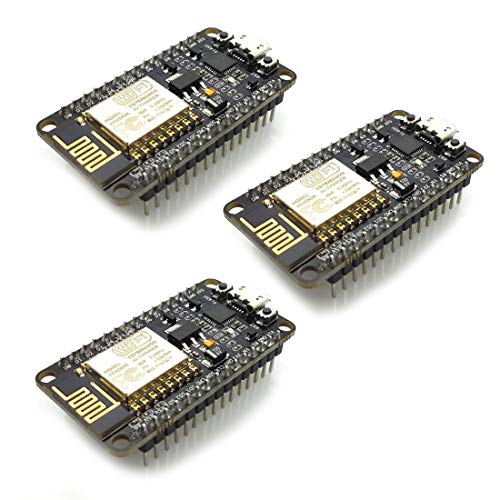
That said, if you do get into ESP in the future, go for something like the NodeMCU module. Generally reliable.
The solder joint might make a minuscule difference in voltage drop, but its more about the length (and number of LEDs) from the power supply than anything else. 12V can go pretty far so you might "bench test" them all before sticking them up on the wall. You might be able to just connect power at the beginning and end and maybe one point in the middle (if doing a full loop around the room). The also make solderless connectors (be sure to get the proper ones for your strip - 3-5 pins) that would be worth trying if you don't feel comfortable soldering.
Nice thanks! Im looking at this one: https://www.amazon.com/gp/product/B08DHMR1LN/ref=ox_sc_act_title_1?smid=A35UAT07QG3EC6&th=1
I'm having a hard time seeing how wide the strips are. They look to be an inch? The dimensions on the page state it's 3.15in but I think they're referring to the box they come in. I'm hoping they fit in the diffusion channels.
The Manta installation was in early June, so it's too soon to get a reading on power supply durability. They're mounted inside the non-sealed structure, and that gives them some protection from sun and direct rain. I don't think I'd ever fully enclose them; it's better to mount them directly to a metal part of the structure (for heat sinking) and expose them to ambient air for convection cooling. At most I might fab a metal "patio cover" to give them some shade and protection from direct rain. The Mean Well HLG power supplies I used seem really well built, and I plan to standardize on these for all my projects. The series runs from 40W to 600W.
The next time I order strips from BTF I'll ask if they can increase the wire gauge, but I'm not optimistic about that. At full brightness the short section of 24AWG wire did get warm, but it's probably still within the ampacity rating of the wire. I'll take some more measurements next time I get a chance to check the the voltage drop across the connector and wire segment.
I plan to write an article on weatherproofing, but here's a good tip I received recently: dielectric grease inside all the connectors. This further protects the contacts from corrosion, and has no impact on contact resistance.
totally not worth it unless you are doing that as a home project (or have 5050 to spare, which i highly doubt it is the case)
​
either solder or this for the splicing, but i have not test that kind of connectors so idk how reliable they are but they exist...
I tried almost every digital ping. I tried with some resistors, from 1k to 3 1k in series. I use this: https://www.amazon.es/Tesfish-Adaptador-Corriente-Transformador-alimentaci%C3%B3n/dp/B083QNN7Z7/ref=sr_1_6?keywords=5v+10a&qid=1655145196&sprefix=%2Caps%2C83&sr=8-6
I am using BTF strips and power supplies. Im not at home right now, but the packaging of the strips says something like 15-45W per meter. I decided to purchase the PSUs with the 45W figure in mind to be safe, but I’ll probably start with just one to see if my strips come in at under ~25W on average. I’ll probably also only start with 3 power injections to see how they hold up.
Another quick question: perhaps I don’t know enough about FastLED’s purpose or limitations, but why would you recommend OctoWS2811 for this?
Lastly, 33 FPS is a bit less than I was hoping for. I would be comfortable wiring up to 8 channels around the room, but as you said, the drawing aspect will probably detract from the theoretical 132 FPS cap. Have you ever seen anyone try to use a BeagleBone or Nano RP2040 to separate the drawing and rendering tasks?
do you by any chance if that one would be compatible
​
https://www.amazon.de/gp/product/B078HYP681/ref=ewc_pr_img_1?smid=A1X7QLRQH87QA3&th=1
it says "64 WS2812-LEDs " according to the github page it should be compatible together with the arduino uno wifi rev2 right ?
Thanks for that I will have a look :)
What is about this one :
https://www.amazon.de/dp/B088W62171/ref=twister_B088JPWJQQ?_encoding=UTF8&th=1
​
should be compatible as well but again the question is whether i have to solder
I'm using WS2815
By fast I mean I mean making change every 600 LEDs to any color and dimming, at the same time, at the same nanosecond. Maybe this is a bit to much calculation.
Besides, are you sure an ESP32 would be good enough ? I first tried with an Arudino UNO then a Mega and the Mega is very just enough, I mean it works for some templates but after 1 or 2 minutes running, everything goes messy.
Would these work (Pack of 10 Pieces) MCIGICM 1000uf 25V Capacitor, Aluminum Electrolytic Capacitor 1000uf 25v 10x17 https://www.amazon.com/dp/B06WGPNM19/ref=cm_sw_r_cp_api_i_PBDXC6MAFB8MDNJNTRR0?_encoding=UTF8&psc=1
I have this LED Matrix that I want to run scrolling text with FastLED.
https://www.amazon.com/dp/B088BTXHRG?psc=1&ref=ppx\_yo2\_dt\_b\_product\_details
I am able to get what you see in the video working with Adafruit_NeoMatrix. I really want to use FastLED to scroll text on the matrix and use some of the noise effects etc and also light the neopixels on the map in the video.
I am sure someone has mapped this out and has it working. I can tell that the mapping is not right, I'm not sure how this is wired and I'm not sure how to do this in FastLED. I have tried the demo from FasLEDMatrix, but the mapping is wrong, so the output is just a mess.
this is good for voltage drop calculator
use both links as reference and see what it needs to be change according to your needs
Reusable ice cubes? https://www.amazon.com/Reusable-Plastic-Cubes-count-Colors/dp/B007JX59FC
Just drain them - ready to go =)
Thanks! Yeah it took me a bit to figure the film out. And it sucks to apply. I got this one - "silver" KESPEN Window Film One Way Daytime Privacy Heat Control Anti UV Non-Adhesive Reflective House Window Tint for Home and Office, Silver, 35.4 Inch X 8.2 Feet https://www.amazon.com/dp/B07QMS3WD8/ref=cm_sw_r_apan_glt_i_63JD96XN543CKQ1X4XBS?_encoding=UTF8&psc=1
Thank you, here is a better picture of the resistors https://imgur.com/a/L8dYDSb
and the LEDs that I'm using https://www.amazon.com/BTF-LIGHTING-Flexible-Individually-Addressable-Non-waterproof/dp/B01CDTEJBG/ref=sr_1_1?m=A35UAT07QG3EC6&marketplaceID=ATVPDKIKX0DER&qid=1644958405&s=merchant-items&sr=1-1&th=1
Three pin weather proof junction connectors with screw terminals work well. Especially if you put some glue filled heat shrink on the wire.
https://www.amazon.ca/FULARR-Waterproof-Junction-Connector-External/dp/B07ZNZ3HB4
These strips commonly have extra pos/neg hookup wires at the start of the strip. It makes it easy to do power injecting when you're connecting multiple strips together. You can see it in this amazon listing, second photo.
https://www.amazon.com/ALITOVE-Individual-Addressable-Programmable-Non-Waterproof/dp/B01MG49QKD/
You just need a RFID reader module like the RC522 that talks via SPI. Then it just takes a few lines of code to initialize it and read it. Plenty of samples out there.
I solved my distance problem by putting the controller and power supply into a weatherproof box close to the display. Then, all I need to the box is line power.
The first time the controller was running FastLED on a Wemos D1 Mini, and reprogramming, if needed, was done OTA.
The second time was also a Wemos D1 Mini running WLED.
If they are 12V LEDs then power at each end is sufficient. If 5V then you need power taps more often.
Our xmas tree has 375 12V WS2812 LEDs and is fed power on each end.
​
​
I also found a bargain for
Assuming you mean the Hexagon lights, here's how I made them:
Starting off, I bought those off the internet and got a 1cm thick
chipboard from my local hardware store. Then I made a sketch on the wood that was about 2cm less in diameter so you couldn't see the lights from the front. After I had cut out the pattern I took some WS2812B strips and glued them to the edges of the wood. After that, I glued the Hexagons to the wood, did some soldering and connected the lights to an Arduino and that's it.
The main reason I suspect side-emitting LEDs are being used is the density of the layers. I'm not sure there would be enough space between the layers for a 5+mm wide strip.
I envisaged all the various rings (or irregularly shaped rings) being fabricated on a single PCB, similar to how the various sizes of off-the-shelf rings are made. See the first image in this listing and notice the rings are attached at 90° increments.
Or why not combine the two and have an SK6812 strip. These should do the trick. 144 LEDs per meter which should give you the brightness you need and a dedicated white led to keep the power consumption down
Yeah alot depends on how much and is the space going to get a decent airflow. But I would say check out some waterproof power supplies as they tend to need to not have fans because being water proof and all. I'm currently using a 100w and 150w of these for my outdoor Xmas lights. They are in sealed boxes which is probably not ideal in most situations. But they are only on in the evening when it's cold and are temporary for the moment.
But check them out. These ones in particular I choose because the were the thinnest and smallest form factor I could find. Some of equivalent ratings are bigger.
VOLTRANS 150W IP67 Waterproof LED Power Supply, Universal Input AC100-240VAC With Plug, 12V DC 12.5A Max. Constant Voltage Output LED Transformer Driver for Outdoor LED Lights https://www.amazon.com/dp/B0952P6SGH/ref=cm_sw_r_apan_glt_fabc_5KW606QXRGMJANJN5HDQ?_encoding=UTF8&psc=1
To do it right and safely, you need a power supply with as many amps as the max consumption for your project plus a safety margin (I like ~50% myself).
How many LED and what is the power draw per LED? Common WS28XX strips consume a peak of 60mA.
So for 10 pixels you would need 600mA plus safety margin. So I would get a 1 amp supply.
I don't think you will find anything much larger than 5vdc 2 amps in the small wall-wart style plug.
5Amp range 5vdc supplies usually come in the laptop style brick.
Once you get up to 10amp or higher, they usually come in the aluminum cage format.
I would be very weary of the smallest power supply you find for a given rating. Chances are it is not truly capable of putting out the rated power continuously.
I just use a computer power supply and a simple break out board. An old computer power supply from a scrap machine might do nicely for you. You don't strictly need the break out board but it does help ensure you don't accidentally connect a 12v power supply line to your 5v LEDs. Definitely no experience with that and I super thought about getting a break out board to prevent this from happening before doing anything stupid and having to tear apart a nearly completed project.
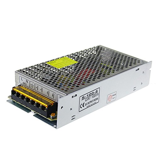
Wow. First power ist dangerous for people that have no clue what they are doing. You have to connect main cables to that thing. I am going to assume that OP is not able to put cable shoes on those etc.
The second power supply is too underpowered for most leds at full bright. WS2812b (most popular RGB LEDs) use 60mA at white full brightness. That small power supply can power ~11 at most, but will likely destroy itself in no time then.
What you really need to get is a cheap adjustable bench power supply. Something like this: https://www.amazon.com/Kungber-Adjustable-Switching-Regulated-Adjustments/dp/B08DJ1FDXV/ref=sr_1_3?keywords=bench+power+supply&qid=1639322814&sr=8-3
You can also switch to other LED types that require different voltages.
For beginners - this should be your first power supply:
(Or something like it, search for "breadboard power supply"). It takes USB power as input and plugs directly into your breadboard.
You might consider using one of these to power it. I bought a pair to run a cloud lamp and it works well (carries more juice than a couple of AA batteries) https://www.amazon.com/Miady-10000mAh-Portable-Charger-Charging/dp/B07XFBN7HX
Since your power requirements are low this should have no trouble pushing the power through USB.
Here's a pair of sketches to stream pixel data from Processing to FastLED. I've tested it from 57,600 to 2,000,000 baud on my Nano with its CH340G USB serial. I'm surprised how quickly and reliably such a naive implementation recovers from the occassional glitches.
I'd love to see the results of your ray-marching.
Certainly not the worlds smallest. A great build and really fun tiny desktop sort of display though! I like that the 3d printed cells not only enhance the display but also nicely hold the pixels for soldering. Nice tutorial.
​
Here's some inspiration for the future. ;) https://www.hackster.io/news/build-an-ultra-tiny-smart-rgb-led-display-matrix-with-the-sam-d21-1ead6e181cde
Aclorol WS2812B 144 Pixels Individually Addressable RGB LED Strip 5V, 3.3ft Programmable WS2812B WS2812 1M 144 LEDs Dream Color Strip Lighting N https://www.amazon.com/dp/B07BKQZLDL/ref=cm_sw_r_cp_api_glt_fabc_SVBRWETZN1GV50KDRX4M
So your recommendation would be to use something more along the lines of the PSU in the link, as opposed to a wall wart style PSU? I like the cleanliness of the wall wart style, but the barrel connector doesn’t seem to be up to the task I need it for.
It's a 5v COB https://www.amazon.com/gp/product/B08HD3ZSQV - I need to run 8 strips of them in conjunction with the 2812 strips. These COB strips are very bright, way better then I expected. I need to fade them in/out and cycle thru patterns.
​
That analog output example is helpful - gives me some ideas. It's more then I found in my searches.
They are 10mm wide 12mm spacing ws2812b... Here are the exact ones although they are standard
HJHX Ws2812b Led Strip-16.4ft 300LEDs Individually Addressable Led Light, SMD5050 RGB Magic Color Flexible Rope Lights with Pure Gold Wire(Non-Waterproof) https://www.amazon.com/dp/B078S6Z9KG/ref=cm_sw_r_apan_glt_fabc_ZN0V5VEA45940Q8SYS16?_encoding=UTF8&psc=1
I can upload the files tomorrow I'll just export them all.
That sucks, but glad you found it. We've all been there! Memory errors are extremely hard to debug, especially on microcontrollers.
Maybe we should port valgrind to ESP32! ;-)
Thanks for the thoughtful reply Marc!
In short: we can do almost anything. The hard thing is to decide what's important and what to focus on :-) This is where I need your (= the FastLED community) help...
Regarding PoV, I did a quick experiment a while ago, you can see the result: https://stackblitz.com/edit/avr8js-pov
No one has installed LED lighting using FastLED for 30 years :-).
I have run outdoor installations around the clock for several years. Some of the gear is from 2004 and has been through multiple installations. We use a different manufacturer, but you want stuff like this, and I recommend using solderseal to make your connections instead of soldering and heatshrinking yourself unless you're really good at it (it's just too easy to have some solder poke out and make a short)
https://www.amazon.com/Core-30cm-Pigtail-Waterproof-xConnect-Holiday/dp/B08MPYXPG1
Hi u/jaireaux - Have your considers using 7 LEDs WS2812b ring? You can find them everywhere such as:
https://www.amazon.com/Integrated-Drivers-forArduino-Raspberry-ESP8266/dp/B08FB14S5P/ref=sr_1_10?dchild=1&keywords=ws2812b+ring&qid=1634060799&sr=8-10
You can try using 12 LEDs ring for your glasses, too.
So I did a thing with an Arduino Mega and an Auto Gain Control Electret Mic Module. I've designed a variety of animations (some music reactive and some not). My roommate said that the animations needed to be "more stimulating" which can be hard to achieve with the FFT sampling delay, so I've sprinkled them in here and there.
The main user input is a rotary encoder with a built in button. I've designed it so that the animations and color palettes are user selectable. Alternatively, by double clicking the rotary encoder you can set it to cycle through color palettes. If you double click it again, it will cycle through animations AND color palettes (which you can see in the video below).
I need to do a little bit of work with the bass response, as our studio monitors and 12" subwoofer in the garage are a little overpowering. The sound reactive animations are much more crisp with my JBL Boombox or Visio 2:1 Soundbar w/ 5.25" subwoofer.
I prefer to use the Electret Mic modules as you get a lot more flexibility with your audio sources, but it definitely has it's drawbacks. I'm open to sharing code if anyone's interested! Specifically with the rotary encoder usage and even animations. But I hope you enjoy.
Also I highly recommend these aluminum diffusers for any strip projects that are outward facing, as it is much easier on the eyes and gives the option to remount the strips with ease: https://www.amazon.com/dp/B01LL3S006?psc=1&ref=ppx\_yo2\_dt\_b\_product\_details
Hello I would use this ELEGOO 32pcs PCB Prototype Carte de Circuit Imprimé à Double Faces pour Board DIY 5 Tailles[2X8cm 3X7cm 4X6cm 5X7cm 7X9cm] https://www.amazon.fr/dp/B073W78G8J/ref=cm_sw_r_cp_api_glt_i_4V4C5G9MY7BM9K4BQR7P?_encoding=UTF8&psc=1 Your circuit is small. I would also as u/Heraclius404 suggested to switch for a cheaper small more powerful mcu. You could use an esp32 that will fit on your pcb. Plus it has Bluetooth so you can change the blinking pattern with your phone. Good luck with your build
I've been working on something similar since my Google-fu didn't find this project for me. It's not close to public-ready, but since this topic came up I figured I could at least describe it. Maybe it would help someone here.
I've written a command-line utility that will take a series of BMP files and convert them into either a *.h or *.csv file. The bitmaps can be any shape, X by Y, as long as they are 24-bit color. For example:
- Have a series of BMP files named JackOLantern001.bmp through JackOLantern010.bmp. They can be made from scratch or converted from a GIF through an online tool. They need to be the appropriate X by Y of your desired LED matrix output.
- On a VC++ Developer Command prompt, enter "bmp2frames JackOLantern".
- Compile switches: (As I said, not ready for the public.)
- Output *.h or *.csv file. Now that I've found this thread, I can probably add in the direct FastLED format, if there is interest.
- RGB or other pixel format.
- Numerical order or serpentine.
- The utility creates JackOLantern.h or JackOLantern.csv as above. The first line has a 4 digit decimal number stating the number of frames in the entire file. I'm debating adding in a frame rate, but we'll see if that becomes important.
The plan is to copy the CSV files to a SD card. The Arduino will read the directory of the SD card and read in the CSV files, one X by Y at a time, sending them out to my LED array via FastLED. Maybe there will be a playlist file to let the Arduino know which files to play in which order.
I'm guessing that there are existing projects that do all of this already, but I felt like writing the converter program. I've had the Arduino Duemilanove and the SD card module for a while. The plan is to put a 16x16 array into a pumpkin for Halloween.
Thoughts?
There are a variety of WS28** sort of flexible panels if flexibility is what you're looking for and want something you can easily use with FastLED. Google "flexible led matrix" search around. You will find square and rectangular layouts.
One example:
https://www.amazon.com/dp/B01DC0IPVU/ref=cm_sw_r_cp_apan_glt_fabc_HJHVKVXHBVD3ZSRFCH11?_encoding=UTF8&psc=1
For future projects, I would recommend some shrink wrap tubing like below.
Much cleaner look, and very secure.
They are finicky sometimes and take a little finesse when inserting. But if you just solder them on the connectors they work well. Make sure you have a pair of plyers to squeeze the contacts to the metal if not soldering otherwise you'll have to tap the connector until it kicks back on every so often. Especially if you have a big subwoofer near by. https://www.amazon.com/dp/B07RPZ49MZ/ref=cm_sw_r_apan_glt_fabc_8TZSB7DZB7YNK21JNY5H?_encoding=UTF8&psc=1
Each one is powered by one of these 12v 200 watt power supplies:
https://www.amazon.com/dp/B07VDRXTSZ/
They get warm during use but no need for cooling or anything like that and they’re waterproof! The power supplies are separated from the lights because I wanted to reduce the weight of the lights themselves.
Have brightness at 30% and we know a draw of 0.6mA per LED at pure white, that is 0.6mA/3=0.2mA per pixel. Then 792x0.2mA=158.4mA. Batteries x3 so 80,400 mAh (26800mAhx3). So 80,400mAh/158.4mA = 507.5 hours at full white.
That's an example but what I used has built in strain relief, which is just as necessary when doing wearables because solder connections don't like to flex either. For my jacket I used something like this but there are other forms that I've used for other wearables but this was what was starting to be available 8 years ago if you ordered directly from China.
Are you talking about something like this or something more like those clothing specific LEDs that can be stitched onto fabric with conductive thread?
The DMX library I’m using is this one:
https://github.com/luksal/ESP32-DMX
Simple and works well so far. I connect the DMX cables to my board using one of these RS485 to TTL converters:
BTF-LIGHTING 144 led/m WS2812B 7.2mm super narrow strips: https://www.amazon.com/gp/product/B08SBTJZV9/
Pricey but worth it. Only pain is the tedious soldering of the tiny pads on these narrow strips.
Okay thank you for the information! I just have these strips already from a friend who was moving and decided he didn't need these so he gave them too me. Otherwise I would've gotten some input before purchasing some strips.
So would a power supply like this work? Or does it need more amperage?
I do have quite a bit ~100ft of 12 gauge OFC speaker wire from recently doing my car stereo so I'll see if that'll work with what the calculator says.
https://www.imrbatteries.com/ is my favorite source for bare cells.
The most recent battery pack I built was a 10S 3P 36V pack for an electric longboard. I used this BMS module:
https://www.amazon.com/gp/product/B075MDQ92X/ref=ppx_yo_dt_b_search_asin_title?ie=UTF8&psc=1
Thank you! I used this. I 3d printed caps that fit over the LEDs with a hole in the top. Then I wrapped bundles of the cable with small rubber bands, then used hot glue to secure them to the caps
Thank you for the kind words, I'm happy you like it. I used this filament and lined the inside of the diffusers with aluminum foil tape
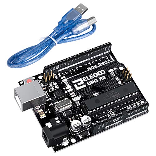
Assuming you can buy from amazon bad are in the states, this will work for boards, 3 pack for $14 https://www.amazon.com/dp/B081CSJV2V/ref=cm_sw_r_cp_apa_glc_fabc_2TY0GX5GFW84CSZXZJZ2?_encoding=UTF8&psc=1
You'll also want some breadboard / protoboard and jumpers to set everything up. I would highly recommend solid jumper wires versus the dupont ones. They are much cleaner and easier to work with in my opinion. Also an Arduino strated kit may or may not have protoboarf and jumpers, but it should have some basic stuff like resistors, push buttons, single LEDs, and other stuff like that which is useful in the long run.
If you're doing just a few less (under 50 addressable LEDs) then you can get away running power through the esp board and using a 5v wall charger and usb cable assuming the charger is a couple amp output.
A flux pen can also help with getting things to go together nicely. Use a little on the strip pads. Something like this:
https://www.amazon.com/Kester83-1000-0951-Soldering-Flux-Low-Solids-No-Clean/dp/B004X4KOWS/
I would take a multimeter and check the voltage to see what might be going wrong. I bought a $20 o-scope on Amazon that’s good enough to at least see the LED data signal (I have no idea how to read it but I can see when it’s there). That might help if you’re really having problems.
They’re directional as I’m sure you’ve figured out, so make sure they’re facing the right way.
Buy some of the LED connectors (these: https://www.sparkfun.com/products/14575) and use those, it’s much better to use plugs then you don’t have to worry as much about fragility. I have literally just soldered one of those to an ESP directly, plugged it directly into an LED strip, and bobs you’re uncle it’s working.
Not directly related but these will save your life if you’re needing to solder wires together:
TICONN 150 PCS Solder Seal Wire Connectors, Heat Shrink Butt Connectors, Waterproof and Insulated Electrical Wire Terminals, Butt Splice (150PCS) https://www.amazon.com/dp/B07HCNTZ2Z/ref=cm_sw_r_cp_api_glt_fabc_BZ9KDGAMHC7WFSWD2E8Z?_encoding=UTF8&psc=1
Use a lighter or heat gun to shrink and solder at the same time. For me that cuts 90% of the time off soldering wires together (which I seem to do a lot with LEDs).
100% correct.Apropos those terminal strips: I have tried all sorts of them that I purchased in the US (Amazon) and have yet to find any that match the quality of the ones I can buy from Conrad Elektronik in Germany. I am fortunate enough to be able to go there on business (pre-CV-19) and always stock up. They are not the answer to every problem, but they are extremely handy.
This is the inside of a dual ESP8266 LED controller I use at Christmas (at that moment in use on the back porch with one controller installed). Installed in a cheap Harbor Freight "ammo box" it handles the weather in TX nicely. I flash the ESPs with either ESPixelStick or WLED firmware depending on the application.
Edit: These are are no better than the ones you used and fall apart as well.
Looks like there are radio controlled versions too. What would it look like to spoof the signal?
https://www.amazon.com/Pinspot-JLPOW-Spotlight-Lighting-Childrens/dp/B07Y4R519D
This is the app. I put LED strips in a dark room and then record the brightness of the app to adjust colour balance hex values. It's not fast, but it makes it kind of brainless.
A flux pen is a good idea! I feel like my solder tips lose useful contact area way faster than I'd like. Tweezers are super useful. Mine are getting all torn up and it would probably be a good idea to get a few types before they end up totally warped :)
For projects like that I have found it much easier to work with WS2812b strings rather then the more common flexible PCB strips.
Thanks Johnny,
I believe you are correct, I tried the workarounds to no avail. I did test some Serial.println debug statements and it created erratic led behavior.
Its unfortunate, because I ordered 5m of strip and track to save money in bulk as my projected needed it, but I will find a use for it elsewhere and my time is more valuable then the money lost.
I am going to order these APA102 knockoffs and want to confirm you (or someone else) thinks these will work?:
The B variant uses gold bond wires. The Eco variant uses some unspecified alloy, so the MTBF is shorter. They're brighter too, if this is correct.
Should be ok. Just a lot of work, oof! Try re-melting the solder joints of the connections going into the pixels that aren't working. The joint might have just worked initially, but after a bit of wiggling become bad.
Consider sizing your board and holes to the strip next time! Or check out pixel strings (not strips) if you have the space in your project to house them.
You can also get these instead of cutting up a strip: https://www.amazon.com/ALITOVE-100pcs-WS2812B-Addressable-Arduino/dp/B01D1FFVOA/ref=asc_df_B01D1FFVOA/
Lots of good info here, thanks!
Enough info that I am really concerned that I am biting off more than I can chew.
First off, to clear up some confusion, I am talking about strings and not strips. Here is an example set from Amazon. I don't know if that changes any of the responses.
I did a white test and the power supply was able to handle it.
I am getting some color drop-off toward the end of the 400 leds string so I am injecting at 250. That seems to have resolved the issue.
I switched out to a different set of leds and I'm getting some flickering on one of the patterns. It's a candy cane chase with three colors. I wasn't getting it with the original string. And this is before I tried sending the signal 20 feet. I temporarily made up of the connections just to test things out so I will go back and see if maybe there is a loose connection somewhere.
The power supply is IP67 and lists that it has overload/overvoltage/overheat/short circuit protection.
I am using the waterproof connectors to get the signal and power to the strings. I had not planned on using them between the strings, though. That's enough to give me pause on the whole project as I won't have enough time to get them and assemble the strings as I have limited decorating time.
What are your thoughts on this: Muzata U113?
The channel is 13mm wide (my strips are 12mm wide), 0.84" height from LED to Cover.
I had a plastics shop actually cut me some acrylic 1/2" chunks to test how well they diffuse - what struck me just how heavy they were! It sure looks nice, but I can see the weight add up. It's one thing if it's sitting on a desk....
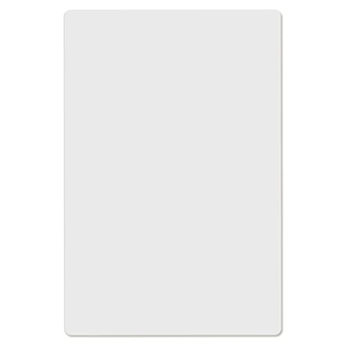
I absolutely LOVE the diffusion. I used THIS sheet with less than spectacular results.
What is the distance between the LEDs and the sheet? Also how did you arrange your LEDs in such a nice spiral?
18 Amps? Wow, so I should get a new power supply? Will something like this work?
KeeYees 10pcs 4 Channels IIC I2C Logic Level Converter Bi-Directional Module 3.3V to 5V Shifter for Arduino (Pack of 10) https://www.amazon.com/dp/B07LG646VS/ref=cm_sw_r_cp_apa_i_ast2DbN44W4S2
Just a no name brand off amazon. Although i believe i have another one coming from adafruit as well
I did the exact same thing. My room is only 12 x 24 though. I bought my 2815 on Amazon, they work well. These are the ones I got.
ALITOVE 12V WS2813 WS2812B LED Strip Light WS2815 Individually Addressable RGB LED Pixel Strip 16.4ft 300 LEDs Programmable Digital LED Light Not Waterproof White PCB for Arduino Raspberry Pi Project https://smile.amazon.com/dp/B07QGD3YHH/ref=cm_sw_r_cp_apa_i_AUobEbC5GMJ2D
I found a good power supply there too. I didn't want an open frame to fill with dust, and it doesn't get too hot even without a fan.
LED Driver 200 Watts Waterproof IP67 Power Supply Transformer Adapter 90V-130V AC to 12V DC Low Voltage Output with 3-Prong Plug 3.3 Feet Cable for LED Light, Computer Project, Outdoor Light https://smile.amazon.com/dp/B07MZRMF21/ref=cm_sw_r_cp_apa_i_UWobEbSD865A6
I ran 14ga wire parallel to the strip and attached it to the strip every 3 meters or so.
The only problem with that strip is that a few of the lights seem to overheat if left in full white for a long time, and then stop responding and get stuck that way till they cool a little. It's only a few, I could replace that part of the strip, but I just limited brightness to 220, and it doesn't happen anymore.
I'm planning to write up my project soon with pictures.
Coding language is C++. It’s all FastLED code. The firmware is open source on GitHub. Android app is https://play.google.com/store/apps/details?id=com.lantern&hl=en_US
Not everything is open source yet, but probably will be eventually. The goal is to make building and controlling LED projects easier and faster. Im also working on some hardware to go with it!
Very nice /u/Yves-bazin , maybe one day I'll add code so that people can stream video from their phone, to my shirt :) https://play.google.com/store/apps/details?id=com.litux.art_net_controller&hl=en_US
Oh boy, I guess I've just ruined a lot of my upcoming time with new projects :)
yep, keep in mind that most breadboards are rated for a max of 1a of current so if you power a led strip through it you'll be creating a major safety hazard (ive seen pictures of melted breadboards from people who've accidentally done this). you can instead solder everything together with blank pcbs and fashion a case for it yourself or 3d print one if you have access to that.
There are 12v WS2811/WS2812. That is, the data level is still 5v but the power is 12v. I personally have been using these ( https://www.amazon.com/gp/product/B06XSFT1VK/ ) because I like how they are fully sealed and since they're not on a strip you can place them better without resoldering everything. I wish there was a version using the same form factor but more up to date protocols, but they do work just great.
The LED power level will be somewhat robust, you might get some brighter and less bright based on load in the rest of the car.
You'll need to step-down from 12v to 5v and 3.3v anyway. My 12v builds include a small buck converter, which will also handle any fluctuation in the 12v line.