
What are
/r/Optics'
favorite Products & Services?
From 3.5 billion Reddit comments
The most popular Products mentioned in /r/Optics:


The most popular Services mentioned in /r/Optics:
SlideShare
Libraries.io
Google Meet
Quora
Cambridge Dictionary
SemanticScholar
CircuitLab
Omni Calculator
SmartDeblur
The most popular reviews in /r/Optics:
This book is fantastic for starting out. It just has so many topics
https://www.amazon.com/Fundamentals-Photonics-Bahaa-Saleh/dp/0471358320
Don’t pay this price for it. I think I got mine for like $50 on eBay.
There’s also a book with the author called Hecht. Just google Eugene Hecht Optics textbook
Unobscured mirror systems end up being huge by comparison with refractive systems.
See: https://www.slideshare.net/operacrazy/godzilla-versus-bambi (rockstar)
Aligning off axis mirror segments is a total pain in the ass; what do you use for a reference point, and how do you define the imaginary mechanical axes that you need to use (that was obvious in the optical design program)?
Lenses are nicely rotationally symmetric; and it's really easy to cut cylindrical bores that are really accurate in terms of centration.
Mirror materials are surprisingly uncooperative in terms of the combinations of grindeability / cuttability / polishability / durability that you might like.
Off axis unobscured systems are also difficult to baffle to prevent stray light.
Fun as hell to design though :)
Look up three mirror anastigmat (TMA) and patents by Lacy Cook (also rockstar).
>See theer you have it again, talking about logic gates which are based on the IO bit system
Er, no, you will need logic gates even here, it just won't necessarily need to be binary. Same as in quantum computers. Those logic gates wold still be constrained by the size of the wavelength of light.
​
>If only someone would start with the basics using the properties of light when experimenting we would already have optical computers by now.
>
>Lukily for me the world is full of retards which will allow me to develop one day an optical processor...
sure,
https://dictionary.cambridge.org/dictionary/english/megalomania
​
Listen, if you think you're a genius and only person on this planet who can think outside of the box then you'll need to provide more proof of how your hypothetical light based processor is going to work other than mere claims of how light has several proprties rather than one and how the world is full of retards who don't get it. That's not going to cut it, nobody is going to take you seriously. This subreddit is not for talking about science fiction and roleplaying as geniuses.
​
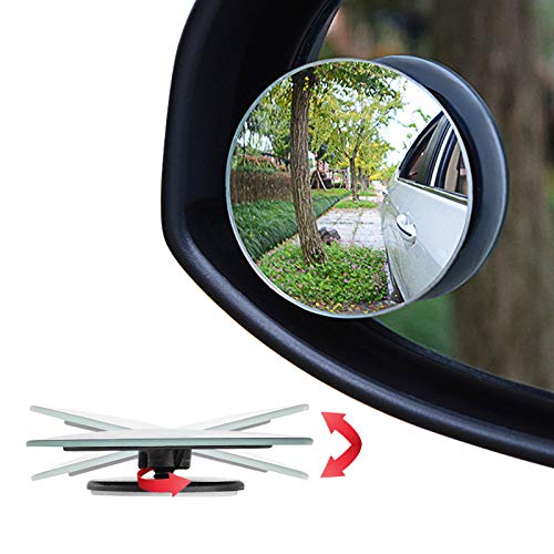
Random guess, but would a consumer grade dome magnifier work?
Just do internet search for "dome magnifier". Amazon and other vendors have tons under that description, such as:
For the Bragg gratings and Angular selectivity physics, I can recommend Goodman's Fourier optics.
RGB seems possible but it is still in research phase it seems. I found this paper where they claim : "enables transparency throughout the visible spectrum at one angle, the generalized Brewster angle, and reflection at every other viewing angle"
I think I read the same article as you about this french startup that has worked out a way to make these curved sensors for way cheaper. But in the very same article they mention that the application field is more astronomy etc ... The main selling point of a curved sensor is that you can compensate aberrations by carefully tayloring the curvature of the sensor to the curvature of the wavefront aberrations induced by the optics in front of it. In any case, I think that you may be a bit confused as to what an "afocal lens" is. I suggest that you first go through an optical design book and then try to work out what you could do with a curved sensor. In any case good ideas can come from anyone so I would not discourage you to search through all this !
Wow. It's wonderful that you're so excited about optics. I have been made fun of in the past for wondering around and looking at stuff through binoculars just because things look so much different through binoculars. One thing that's cool to notice is that in addition to the magnification, there's a distance compression that goes on. For instance, if there is one tree close to you, and another further away, then they'll look much closer together through the binoculars or telescope. Take notice next time you have a look. I always thought it was like those old 3d viewers with the slide wheels, which I really enjoyed as a kid.
I don't have a solid book recommendation, unfortunately, as most of the optics books I own are textbooks. This one from Amazon gets pretty good reviews, however, and is relatively inexpensive, but from the reviews it sounds like you should have some background in physics: http://www.amazon.com/Introduction-Modern-Optics-Dover-Physics/dp/0486659577/ref=sr_1_1?ie=UTF8&qid=1431040075&sr=8-1&keywords=optics.
As for astronomy, and telescopes, I think this book is the absolute best: NightWatch by Terence Dickinson. I started getting into amateur astronomy with that book. It has information on telescopes and binoculars and eyepieces, and how to choose them. It has information on the things you can see, how to read star maps, pretty much everything a beginner needs to know. I bought a few other astronomy books, but I always kept going back to this one. http://www.amazon.com/NightWatch-Practical-Guide-Viewing-Universe/dp/155407147X/ref=sr_1_1?ie=UTF8&qid=1431039313&sr=8-1&keywords=nightwatch+book
Use a spherical mirror, and accept the coma / astig for using it off axis.
6" 1.3m EFL mirror, $70. Amazon. https://www.amazon.com/160mm-Telescope-Spherical-Mirror-1300mm/dp/B01N7A6T6Z
...or maybe time to learn how to drill mirrors :)
The devil is in the details here. This is in reality an interplay of the origin of the input electric field, the position of the aperture and whether or not this is a far-field imaging system (z >>> d), or a lens/mirror imaging system (z ~ focal length). If it is the latter, then the position of the lens with respect to the aperture also plays a part.
I think on of the things that might mess you up is that people say that the electric field in the far field is proportional to the fourier transform. And this is true! But there are a couple phase factors that are usually neglected because they don't matter for the intensity patter. However, these are exactly the phase factors that would help you here. I would suggest looking up the full equation for the Fraunhofer diffraction pattern. You can find it in Fourier Optics by Goodman (https://www.amazon.com/Introduction-Fourier-Optics-Joseph-Goodman/dp/0974707724). I don't have access to it at the moment because I am traveling. Are you part of an university? They might have a copy of it. There are of course also pdf versions floating around on the web.
https://www.edmundoptics.com/p/254-x-381mm-pfl-90deg-off-axis-parabolic-silver-mirror/35990/
https://www.amazon.com/Chanzon-High-Power-White-6000K/dp/B01DBZJBIW?th=1
Thats the OAP and the LED I am using. I believe the LED is smaller than the FL of the OAP. As for beamline, I am following the standard procedure - the longer axis of the OAP is parallel to my optical bench surface - which is parallel to the beam I would like to collimate.
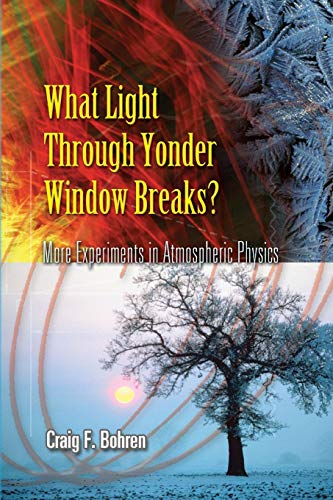
Oh, there is basically exactly the same phenomenon described in https://www.amazon.com/Light-Through-Yonder-Window-Breaks/dp/0486453367/ , chapter 3.
Due to the fabrication process, the plane window can act as a retarder. Sky light is also partially polarized, , and I'm assuming your glasses have polarizers. When you combine polarizer-retarder-polarizer, you can have funky colors like that. Here is the process according to Bohren:
> Light emerging from the initial filter is polarized perpendicular to the transmission axis of the (crossed) final filter; hence, no light would be transmitted by it if there were no interposed retarder. But the retarder transforms this linearly polarized light into elliptically polarized light, which is then incident on the second filter. At least some of this light is transmitted, the amount depending on the retardance, hence on the wavelength.
You can buy entire books full of different phase unwrapping algorithms - why do you think it's as simple as "open github, take code" ?
For a more practical overview, here's this textbook: https://www.amazon.com/Handbook-Raman-Spectroscopy-Laboratory-Practical/dp/0824705572
It covers the basics of Raman scattering theory, system setup, and goes through a variety of applications.
Here's a second textbook if you want a deep dive into Raman scattering theory in terms of both classical EM and quantum: https://onlinelibrary.wiley.com/doi/book/10.1002/0470845767
If you have an idea of what kind of system you'll be building (source type, what kind of detector, etc.), I can point you to some papers as well.
For in process cleaning I have always used plunger style bottles like this. We have one for soapy water, one for methanol, and one for acetone. We use the bottle to wet a cloth, then wipe the surface. Usually ordinary Kleenex. The acetone doesn't react with this type of plastic.
This is all for cleaning and inspecting uncoated, unmounted glass or hard crystals. Methanol can subtly interact with mounting materials. I have seen I embrittle some plastics and corrode aluminum.
I am used to using dispenser pump bottles like this. Pushing down on the metal cap fills the little reservoir on top that you dip the paper or cloth into.
Rather than paper, I prefer the polyester clean room wipes, but of course they are more expensive. I find the main trick to any wiping technique it to wipe slowly enough that the solvent evaporates at the trailing edge before it gets left behind. This allows the contaminates to be drawn up into the cloth. It is one reason why fast-evaporating acetone makes things easier. Also make sure the folded edge is flat against the surface, with no wrinkles.
Some more context would help. For example, if you are okay with ophthalmic grade glass lenses you could buy a trial lens kit. That's a huge number of ~36mm diameter glass lenses for a pretty low cost.
Ophthalmic grade standard lenses yes there are standards (0.25D increments of power, etc). The optical engineering world has not standardized to the level of the ophthalmic world.
An example trial lens kit: https://www.amazon.com/Trial-Illuminated-Frame-Standard-Case/dp/B010NP50UG/ref=sr_1_8?crid=3PLJZWRL1HOSW&keywords=trial+lens+kit&qid=1648680458&sprefix=trial+lens+kit%2Caps%2C72&sr=8-8
In the field of holography there is this, although the code is there as an application and the physics is derived and explained "the old way".
https://www.amazon.com/Introduction-Modern-Digital-Holography-Matlab/dp/1107016703/
Are you just trying to build an interferometer or do you have a specific experiment in mind?
Here's something you can get from Amazon
https://www.amazon.com/Cei-World-Michelson-Interferometer/dp/B08CVCL398
Thanks for the recommendation. I figured there would be a handy solution that I'm just not familiar with. I actually have an arduino kit laying around in my room which I never tried using, so I'll use that!
What do you think of these? You think these will be sufficient?
As backup for using the LCOS / DLP: Google Glass Teardown. This blog shows how google glass uses an LCOS screen, and actually shows the exact optical engine we are using in our prototype from the AAXA Pico Projector
Thank you for the suggestion, but I have one actually. This thing: https://www.amazon.com/Celestron-Handheld-Digital-Microscope-Pro/dp/B00CMJ1I08
The picture is pretty decent but, because I'm using it for hand engraving, the latency is a big problem. After a lot of tinkering with the settings I was able to get it down to what feels like ~300ms latency, which is workable but adds quite a bit of difficulty.
At this point I'm approaching it more as a learning experience and an interesting project than a money saving venture, so some non-optimal expenditure of time and money like this is expected fosho.
Look for digital microscopes too. You'll be observing your work on a monitor.
If you think you'll make it cheaper ( similar to this https://www.amazon.com/dp/B00A15N33 )- your time, materials, errors, etc - way to go.
Based on the pictures I'd guess:
The TO package contains both laser diodes. You can't manually turn off the red LD because they are hardwired in there together. Also with only one visible lens, maybe that's to cover both LD collimations.
And the little dot on the left hand side looks like a photodiode, being sensitive enough to capture the expanded LD beam. To be fair sometimes they all blend together and look alike at a distance.
What you can do to test this without cutting a pin is to get an IR blocking filter like this: https://www.amazon.com/Quanmin-Optical-filter-Blocking-camera/dp/B015R07LPO
Place this only in front of the TO package (make sure you're using the lens as well). If there are two diodes in that one TO package it won't work with the IR filter in front.
You could also find an IR pass filter like this: https://www.amazon.com/Fotga-Adjustable-Infrared-X-Ray-Filter/dp/B0179HHJP0
Same idea but you're blocking the red LD and it should work with and without the filter in front of both ports.
Right. But I would need a back focal length of 0 if I want to magnify directly what comes into contact with the back surface of the lens yes? If I have a ball that is 10mm and a focal length of 5mm, does that then mean that it can focus directly on its own surface?
Im looking to literally etch or draw on the surface of the lens itself.
I found: https://www.omnicalculator.com/physics/lensmakers-equation
Just trying to understand it now...
> So the beam size (radiaus) should be 3 mm (at 5 m) + 0.3 (half-divergence)*15m = 7.5 mm and the area ~177 mm^2. That's not bad at all.
1) Why 7.5mm of radius? I did a different calculation:
Distance: d=20m Beam Divergence: θ =0.6mrad
Radius of spot at 20m: x = tan(θ )*d = 12mm
2) Will this lens work?
f=22mm. Diameter=38mm. It's only 5USD, cheaper than yours. I really haven't checked about reflections losses, not sure if it's important
3) >But even 10x10 mm PD has reasonable rise/time fall of less than 100 ns.
We will use 10BASE-T, so the signal will be 100ns. Do you have a photodiode (red wavelength) with that big of an area?
https://www.amazon.com/Raspberry-Industrial-External-Trigger-Monochrome/dp/B085VQ9BBY
Search for monochrome camera no ir filter. By default most cameras will have an ir filter. I don't know how trustworthy this vendor is but it is advertised as having no IR filter.
I've built these before.
I used one of these for my hemisphere: https://www.amazon.com/gp/product/B003HNVXLW/ref=ppx_yo_dt_b_search_asin_title?ie=UTF8&psc=1
Cut an extra hole in it. Then cut it into two pieces.
Spray paint the inside with flat white krylon paint.
Tape the two halves together.
Use a roll of tape as a stand.
Done.
What's your budget?
For $8 you can use your eyes and brain:
At risk of completely offending you (again; hah!)
Did you see this bolt-on to Geary's text?
https://www.amazon.com/Synopsys-Supplement-Introduction-Dilworth-Paperback/dp/B011SKJYGG
Yours for only $902
Code V, yepper. I didn't think that the learning curve was much different than Zemax. CV documentation is much better (but there's much more of it). Their customer support is fantastic. I think I've had 24 hour or less turnaround on all but my most esoteric questions.
Have you taken the introductory CV course that's offered? The cost is included in your license fee, and well worth it. Used to be 5 days at their site, now shortened to 3 I think, and likely zoomed.
Julie Bentley has a book that incorporates using Code V into the lens design material. I didn't care for the writing style very much, but the content might be useful to as a fast translation from previous Zemax workflow to the newer CV.
https://www.amazon.com/Designing-Optics-Using-Code-V/dp/1510619739
I think of Zemax as an optical design program with a nice GUI, that supports macros.
Code V is more like a macro-driven optical design programming language, with a supporting GUI.
I do all my work from the command line / macros. This is because so many lens-setup tasks are repetitive, and forgetting a check-box can be catastrophic. I can also add comments / annotations to remind myself exactly what it was I was doing and why. About 80k of sloc over the past 5 years or so, last time I checked :)
E.g.: the following macro adds a rotationally symmetric kinoform to a surface, and sets the r^2 phase coefficient as variable to be optimized. It sits in a file "kino". To use it "in kino n" where n is the surface to make diffractive. Easy.
! //---------------------------------------------------
! make surf a kinoform
rfd 0
^rw == (REF)
^wl == (WL W^rw)
S#1 ! jump to surface
dif doe
HWL ^wl
HOR 1
HCT R
BLT KIN
! Vary Coeffs - just the first one usually
HCC C1 0
! HCC C2 0
! HCC C3 0
! HCC C4 0
! //-------------------------------------------------------
I don't believe that just a diffuser is really going to be particularly useful here.
It seems that you need add to more sources (extra light is better), spread them out as much as you can (bigger sources cast softer shadows) and then maybe add a little bit of diffusing (to soften your shadows a bit more; I doubt this will help much).
Bear with me for a bit - this is going to sound a bit crazy. Hope you've got some $, hours, and e.g. a machine shop to help you.
If they can be synched, perhaps buy a second macro lamp, attach it rotated at 90° if you can, and see if four lamps helps (probably won't as much as I think you want it to; they probably need to be spread out a bit)
If you're mechanically handy, spread the lamps out a little bit (a few extra inches maybe; cut the lamp housings off, add little metal arms or something for attachment) and see if that works.
If not, try turning the lamps around and bouncing them off the inside of a diffusing hemisphere. I've used these: https://www.amazon.com/gp/product/B003HNVXLW/ref=ppx_yo_dt_b_search_asin_title?ie=UTF8&psc=1 for similar projects (e.g. homemade integrating spheres). I cut them in half, cut a second hole (exit port), spray paint the inside with flat white krylon paint then glue / tape the two halves together. You might cut in half, paint the inside, and poke your lens through the already present hole.
Just a bonkers idea.
Gotcha. Any Radiometry/Polarization books you recommend? I'm considering the following...
Traditionally, going from apc to upc is hard due to the air gap that gets created when mating them together. Not many places sell them, but I found this link on Amazon https://www.amazon.com/dp/B00FX3WK6Q/ref=cm_sw_r_cp_apa_fabc_V4PQFbGJPVP7T You can try these, but I would plan to have fault sizable insertion loss. Not sure if your application can deal with that or not.
United Scientific LCV108 Glass Double Convex Lens, 100mm Diameter, 200mm Focal Length https://www.amazon.com/dp/B00ES3U5LY/ref=cm_sw_r_cp_api_i_M2B3Db4K713H0
I found this on Amazon with a simple google search. It looks like it’s 100mm in diameter, but this was my second result so a smaller one can’t be that hard to source. All planoconvex really means is that one side of the lens is flat and the other side is convex.
So, I finally got the other parts in. The image is effected, but not by much (kinda' produces a soft focus image for an area of the screen).
I'll try you instructions.
I assume you aren't talking about beer in reference to "high purity IPA".
I tried searching for "optical index matching fluid" on Amazon and came up with nothing. Maybe this stuff](https://www.amazon.com/Gamma-Optical-Cleaning-Fluid-Flammable/dp/B017TMF38K/)?
Most of the optical glues seems to be designed for cracked surfaces, rather than just a surface scratch. If you know of a glue that would work better for scratches, I'm all ears.
My other thought was to use some aluminum polishing paste very locally on the scratched surface.
They are $8 on amazon. https://www.amazon.com/Dichroic-Glass0-50-50-5inch-Colorful-Combiner-Splitter/dp/B086VCDXNJ/ref=sr_1_22?dchild=1&keywords=dichroic+cube&qid=1589222409&sr=8-22 I have one in my office, but I don't know what the transmission per side for wavelength is.
The only book that specifically details catoptric optics only is "Reflective Optics" by Korsch.
Take a look:
yes, you will have to "pipe" the light somehow. You can make a mirror-cone out of mylar and have the LED at the larger end and the lens at the smaller end, for example [assuming the mylar doesnt melt -- otherwise aluminum foil maybe]. one way or another you need to put a "stop" in front of the square LED to make the output not square [preferably just at the image plane, right after the light pipe, with the LED itself behind the image plane].
> https://www.amazon.com/dp/B01DBZIY26
just FYI you need a very strong heatsink to prevent lamps of this type from burning themselves up (i found that a big copper CPU sink+thermal grease+a big fan ... was NOT enough. next time will try water cooling). but they are unbelievably bright. i had a 100w led flashlight i built, called it the "torch of zeus".
so unfortunately the only person i know who actually claims nm-sizes is the guy from that one ebay selling silver
i assume the only reason this silver dust is manufactured in the first place is for holographics (the reason i bought it, is to try to make my own holographic emulsion with gelatin) so it may not be common for other materials. because most powders have a distribution for particle sizes, it is possible that you may be able to separate the smaller ones yourself using something like a cyclonic dust filter - im not sure tho (eg, separating by density using centrifugal force just like in nuclear refineries). if you succeeded in doing that you could start a business :)
i think i searched for "nano powder" or "nm powder" something to that effect.
Excel came to mind to me as well. Nakajima, "Optical Design Using Excel: Practical Calculations for Laser Optical Systems" sounds close to me, here's link to Google Books and Amazon below.
Design software for these sorts of optics usually costs several thousand dollars and requires a pretty high degree of optics knowledge to operate competently. Look for books on illumination optics, like this one, for instance:
https://www.amazon.com/Advanced-Nonimaging-Illumination-Optics-Koshel/dp/0071598510
Look into software packages like Optistudio, FRED, or TracePro, and prepare yourself for the long journey ahead.
Hi! Thanks for the response! When you say lens area, are you referring to the aperture size?
Dereniak and Boreman - that's not a book I'm familiar with - is it this one? Is it a good resource on radiometry?
I will PM you my e-mail - seeing some problems worked through would be super helpful.
Best book I've read on shop techniques is Twyman's Prism and Lens making. It is written by the same person who designed the Twyman-Green interferometer form that is widely used in optical testing.
http://www.amazon.com/Prism-Lens-Making-Second-Edition/dp/0852741502
Sure!
Just have to find the right material constants. They can understandably vary quite a bit in PET, but "86% transparent!" doesn't help much without material thickness :-|
Would you happen to know - is there enough play in the visible light range to dodge some some of the attenuation in theory? Like; will higher frequency lights pass through better? Won't help with my design I don't think - I was testing with these crazy bright diving lights and I could only get through a few sheets.