
What are
/r/hardwarehacking's
favorite Products & Services?
From 3.5 billion Reddit comments
The most popular Products mentioned in /r/hardwarehacking:


The most popular Services mentioned in /r/hardwarehacking:
OpenWrt
AnonFiles.com
HackADay
Kali Linux
Chromium OS
Linux kernel
Magic Lantern
The most popular reviews in /r/hardwarehacking:
Just check the headphone port output voltage. I’m guessing it’s just a solid 6v. If so, just buy a battery pack and a 3.5mm female jack, wire them together and you’re done.
Edit
Yeah. That’s exactly what it is. I did a quick google search and the first hit was this YouTube video: https://youtu.be/_dWS3F7UDq4
Here’s a USB adapter that she linked to in the description:
Unlimited Activator, Light Therapy Acne Mask USB Power Cable for Unrestricted Sessions by LiiHot https://www.amazon.com/dp/B07RHW8K35/ref=cm_sw_r_cp_api_i_HpChFb0PBVB5B
In short, it would be pretty hard. See the Magic Lantern project for what you're describing for a huge number of Canon cameras: https://magiclantern.fm/ <- in particular check out the forums for just how much work and skill goes into reverse engineering the firmware and hardware and reimplementing it from scratch.
https://www.kali.org/blog/emergency-self-destruction-luks-kali/
I'm assuming you want something along the lines of this. If you are running a debian based environment you should be able to set this up.
Thanks a lot for your help! So it's just a normal solder? I thought that it would have been harder because there aren't pins on which I can apply soldering iron (https://openwrt.org/_detail/media/vodafone/vsr/hhg2500_uart.jpg?id=toh%3Avodafone%3Avodafone_station_revolution)
What you've given us is not enough. It's just a connector. This is equivalent to just showing us a picture of a DC barrel jack...we have no idea of knowing what voltage is expected on the pins. Look for a label anywhere on the enclosure, maybe on the bottom. That's where information such as expected voltages and maybe adapter model numbers can be found.
If there is a full size 3.5" hard drive inside, I expect that it probably requires +12V and, since it has 4 pins total, a +5V line as well. But we'd never know what the orientation is without taking it apart.
Honestly, even if you were able to find a suitable adapter for it online, it'd be a hell of a lot easier (and probably cheaper) to just get the hard drive out of the enclosure and hook it up inside a desktop or spend like twenty bucks to an adapter like this.
Lastly, please read the sidebar before you post in a subreddit... because this is a bit off topic.
There are some like this, but the quality is very hit-or-miss. https://www.amazon.com/B-Key-Bandwidth-Expansion-Require-SI-PEX40142/dp/B07WDM3H9Z?th=1
This article shows there were some 4x ones made by Dell/HP, I'm not sure if consumers can get them. https://www.servethehome.com/the-dell-4x-m-2-pcie-x16-version-of-the-hp-z-turbo-quad-pro/
I suppose they would probably follow that same practice on their cable tv boxes, hmm. That's good information.
I do have this coming in the mail on Wednesday: https://www.amazon.com/dp/B07WX2DSVB?psc=1&ref=ppx_yo2ov_dt_b_product_details
you think that will cut it for further testing?
This is an example of what I'm talking about. There are a million vendors selling the same cheap Chinese kit under different names with slightly varying accessories all for about the same price. Click around the similar products, and you'll see what I'm talking about.
There are also adapters that transmit hdmi over ethernet. It is not wireless but might solve your issue.
What about this thing? I thought about purchasing it myself price isn't bad considering where sbcs are at the moment....
Can you clear up some assumptions? Since you called them 'TVs' I assume you're using HDMI. Where's the audio coming out of? Is there a separate sound card, or is that getting automatically piped into the HDMI, too?
I think splitting the HDMI audio into TWO separate channels is easy enough, if your TVs have a 'balance' control. Just set one all the way left and the other all the way right. :D But I don't know how you could isolate the 3rd and 4th channels. Maybe set the third to CENTER and EXTERNAL L&R and just don't plug in a L and R.
That said, I don't think basic HDMI technically supports more than 2 channel of audio, and all the other channels are encoded somehow...?
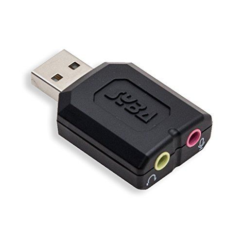
So I am assuming a single sound card with 5.1 outputs or something, and you're just using FL, FR, and CENTER channels. Will your software support three sound cards?? USB sound cards like these are super-cheap, but I don't think I've tried more than one at a time on the same PC.
If you have separate audio signals, you could patch together a bunch of these to insert the correct sound card audio channel into each of three HDMI streams.
Lots of options, but they're all sort of janky and it all depends on your requirements.
The video encryption for Blu-ray is called AACS. It has nothing to do with security related to remote control of the Blu-ray player, which is what the OP is asking about.
OP: see if the Blu-ray player manufacturer has an official Android/iOS app for remote control over network, or if a third-party app like this one includes support for your player.
If you can find a remote control app, the next step would be sniffing the network traffic between the app and player. The easiest way to do this would be running the app in an Android VM on your PC and using Wireshark to snoop on the connection. From there, if you're lucky, it would hopefully be a very straightforward exercise in reverse engineering: click button on remote app, see what the app sends to Blu-ray player over the network in Wireshark, rinse and repeat.
You can get some pretty inexpensive oscilloscopes that would be fine for inspecting UART signals. There are others, but this was the first I found for <$100: https://www.amazon.com/Hantek-HT6022BE20Mhz-Digital-Oscilloscope-Bandwidth/dp/B091SSF8TC/
If you're fairly certain that the test points in your photo are a UART, then voltage alone might help you figure out which one is TX (from the board). But, if you use a multimeter to do this, then, depending on the response of your multimeter, and depending upon whether the TX line is actively transmitting as you measure it, you may not be able to tell exactly what voltage the port is running at: 1.8V TTL? 3V TTL? 5V TTL? +/-12V RS232?
It'd be better to put a scope on the pins and see if you can see something that looks like UART traffic on the line, which would quickly tell you more about any UART signal present, including voltage and baud rate.
If you are keen on giving this little router an extension on its lifecycle, I would say you need to install Linux on it. More of a software hack, but you’d have to check if that’s even an option for you - https://openwrt.org/toh/start (fyi there do exist other distributions that also do the same job, happy hacking!)
I don't want to discourage you, but I really don't think trying to get the existing board to work is a good use of your time. There's just too many things integrated all together for a very specific use-case.
- The Qi coil might be standard, but that row of capacitors is strange to me. They might be doing some dark magic to get the coil matching. I wouldn't want to try replacing it. By the way, in your closeup picture where you guessed you saw a charging circuit, everything in that shot is a capacitor except for the large black square. Nothing useful comes out of that block alone, I'm afraid.
- After that is a Qi receiver. This is really complicated. Above just taking the AC from the coil and turning it into the correct DC for the downstream devices, it is also constantly in contact with the transmitter to adjust power.
- After that is probably a power supply that turns whatever comes from the Qi circuit into power suitable for charging batteries.
- Then that goes into a pair of battery chargers that detect the state of connected batteries and adjust the power to match. That's what you're seeing at the pogo-pins, by the way: The charger is looking for a battery, doesn't find one, and turns off the power.
You really only need the first two, and those are provided easier from existing modules. I'm talking about these modules. They are cloned everywhere at different prices, but they're all pretty much the same thing.
Necroing this, but I made a similar one with a raspberry pi zero. using this https://smile.amazon.com/gp/product/B07H8ZY89H/ for a screen. Soldered a USB audio card ( https://smile.amazon.com/gp/product/B077RBJXP8 ) and stuck a 18650 battery and charging circuit in it. fits within a reasonable form factor.
This? Cool as hell, but 160x100 display and the effort to decode/replace? Cool, but nah.
This is a right one with a caveat - it needs to be heated after application. So unless you have a way to remove the PCB and place it on an iron to heat go with something else.
I didn't use this particular one (we have those paints in many electric part stores in my country) but it should be easier to use.
If you're selling smaller items, this may be a container you could adapt to fit your purpose.
You might just have to Jerry rig something together.
If you own (or are willing to buy) the dongle, then it should be possible to sniff the signals on the connection and reverse engineer it to make a compatible WiFi transmitter that can connect to HASS via MQTT - but without one it will be very difficult unless the device exposes something obvious and well known. The FCC filing you linked looks to be a for a 900mhz radio dongle rather than the 2.4Ghz WiFi smart-home version, but the interface with the door controller will be the same presumably. The silkscreen labels suggest that it operates at 3.3V and the connector is just a straightforward pin header, so jimmying up a quick and dirty interposer on some protoboard to break out the signals for a logic analyzer would be trivial.
Regarding the ultimate HASS implementation though, you might have more luck analysing the APK of the Android version of the OHD app. If you can understand how the API for the cloud service is implemented then you can reimplement it as a HASS.io integration, and then just let the official dongle do its thing. The work might already have been done for you: https://www.home-assistant.io/integrations/aladdin_connect/ (Aladdin Connect, a related product run by The Genie Company and who look to be owned by OHD, already has a HASS integration - and if you take a look at the OHD app's APK, it's full of aladdinconnect.net URLs - I suspect it's the same platform behind the scenes. The FCC filing you posted was by The Genie Company too.)
Would something like this work?
​
If that's how the chip is programmed, that's how it is. You can't change the programming.
Why does it need an IR receiver? If you want it on all the time why not just unsolder everything you don't need, them connect the terminals direct to the supply.
I don't know if there's power management on there either keep that, or only ever plug it in to small supplies.
I personally hate USB devices that have no input. I think USB is the wrong connector. I would probably cut the USB controller off, and attach a battery supply instead. Then it's also portable. i.e make it into something like this https://www.amazon.co.uk/dp/B0816KMQ69/ref=cm_sw_r_cp_apa_fabc_dlT1_6PGQADJ3AZVP97EQSFER?_encoding=UTF8&psc=1
So that might actually be a thing. Yesterday I was doing it on linux, but putty I was only trying on windows so that might be the issue. Ill look into an ftdi driver and see if I have it.
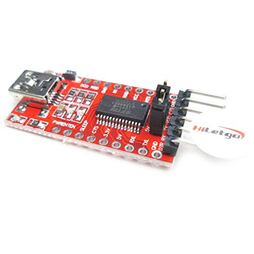
I have tried it on the shikra and a FT232RL (https://www.amazon.com/dp/B075N82CDL/ref=cm_sw_r_cp_apa_i_-IcOFb9EEM6WX). I couldn't get a response from either of them.
I might whip out my pcb work station (https://www.thingiverse.com/thing:3615910) and try it with the probes. My rx had a weak solder joint yesterday so I might pull the pins off and clean them. Then try connecting using the nano probes instead.
I havent looped back before. So I could just add a jumper between tx/rx then connect it to putty. What would the output look like?
Sure it's possible, but the IR sensor is only the start of a long process, so you are basically trying to make one of these from scrap parts.
You'll have to find a special purpose IC or program a microcontroller, make the supporting electronics and maybe write the device driver if necessary.
There are tons of Arduino projects on TV remotes, if you are interested in that kind of stuff. I would recommend buying breakout boards as well.
Sorry, I now see it was unclear. The device on the left of my illustration is a working mini traffic light sensor that lights up. I’m just looking to connect the LEDs to my full size light via SSR.
It has the sensor and functionality built in. STKR Concepts 00-246 Adjustable Garage Parking Sensor Aid, Dark Gray https://www.amazon.com/dp/B00W9EBF0Y/ref=cm_sw_r_cp_api_i_gVEnFbXMMQ9WW
There are several on the market, this is just the one I’m using.
That looks like an old drive, You might look at something like this to get your data off to something else. I really would not go looking for a specific power supply for that unit, just transfer the data via a dock.
If you need to keep the drive, it would be simply easier to put the drive into a new case like this one: https://www.amazon.com/Acomdata-Samba-3-5-Inch-Enclosure-SMBXXXU2E-BLK/dp/B000VNJD18/ref=sr_1_8?dchild=1&qid=1595118694&refinements=p_n_feature_keywords_browse-bin%3A5871549011&s=pc&sr=1-8
In the audio world, we use a device called a DI box to do very similar things to what you're talking about .
some have a "line/speaker" switch on them to switch between line level audio and speaker level audio. This switch adds a resistor based voltage divider to the circuit which attenuates the output signal.
Car stereo based "line output conveters" are effectively the same thing without the isolation/balancing transformers that DIs tyipcally have.
if you're based in the us, this kicker line out converter would do the job for you
But it really is just a fancy voltage divider - if you have high watt resistors you can make the same thing yourself.
Edit: Be prepared for fun noises from fun sources with grounds and the like.
As u/enp2s0 said, the digital out will give you solid results. sometimes the digital output from the tv is fixed volume, so you wouldn't be able to change it with the tv remote, but that is model dependent.
Again, if you're us based, toslink digital to analog converters are widely available as well
That would allow you to connect via the toslink output.
A word of caution with these converters - sometimes they emit a "pop" when changing between sources and channels on the tv, that is dependent on the model of the converter and the tv alike.
There are a number of projects out there doing this very thing with standard desktop power supplies. You might be able to do something similar to:
https://makezine.com/projects/computer-power-supply-to-bench-power-supply-adapter/
On the other hand, mucking about with power supplies is dangerous and there are cheap bench supplies to be found:
https://www.amazon.com/YaeCCC-Variable-Adjustable-Bench-Supply/dp/B074C86DSY/
Let us know what you end up doing.