
What are
/r/CNC's
favorite Products & Services?
From 3.5 billion Reddit comments
The most popular Products mentioned in /r/CNC:


The most popular Services mentioned in /r/CNC:
HackADay
Google Drive
Inkscape
FreeCAD
Aliexpress
Youmagine
Autodesk Tinkercad
Alibaba.com
JustPaste.it
Notion
Microsoft OneDrive
FileDropper.com
VirtualBox
Chrome Remote Desktop
SOLIDWORKS
The most popular Android Apps mentioned in /r/CNC:

The most popular reviews in /r/CNC:
Machining the chocolate directly is going to involve a lot of complexity.
For starters, you'll have to make your whole machine food safe. That means it will need to be sanitizable and your cutting bits will have to not leave any hazardous chemicals or metals behind.
Beyond this, you now face the challenge that chocolate has an extremely low melting point and is therefore likely to melt rather than cut. When I've seen people machine chocolate its typically done in a freezer for this reason.
A simpler solution might be to machine something like jewlers wax into a positive of what you want your chocolate to look like. Then cast the wax in a food-safe silicone.
Once you have that the silicone mold should be able to safely cast the chocolate, and should be reusable to boot.
So honestly, unless you are cutting curved profiles, there's no need to get into Fusion just yet.
I do easily 80% of my lathe work in MDI mode, typing the program directly into the controller.
In your case, you've got:
A facing operation;
An OD turning operation;
A spot-drilling operation;
A drilling operation;
A boring operation; and
A parting application.
Each one of these operations is dirt-simple to program independently by hand, once you know the OD of the stock, the diameter of the drill you will use to rough out the centre bore, and some feeds & speeds appropriate for the machine. The machinist will have guidance here.
The only thing at all "tricky" is if you want to get cute and cut chamfers/deburr with the turning, boring, and parting ops. Otherwise, this is ideal beginner g code stuff.
For now, assume:
That the stock is 0.625 OD;
You will use a 11/32" drill to cut the centre bore;
The tool number is the same as the op number;
A max depth of cut as 0.030" on turning, 0.010" on facing, 0.005" on boring;
Feeds of 0.015"/rev on all ops;
Drill pecks of 0.25" with full withdrawal per peck;
Parting tool is 0.15" wide and can cut 0.400" deep on the radial; and
Boring tool is small enough to fit the drill hole.
Many of these parameters will change on the actual machine (one in particular is a little fast) but as a first exercise, this will do.
You should have this as a reference:
https://www.amazon.com/Programming-Handbook-Third-Peter-Smid/dp/0831133473
And you team should have this as a reference as well.
https://www.amazon.com/Autocross-Win-DGs-Secrets-developing/dp/1521406987
Good luck!
Do not have any CAM software in your shop, or are just doing this one job by hand to learn? If it's the former then that's disappointing because there are many inexpensive CAM programs for simple 2D stuff .
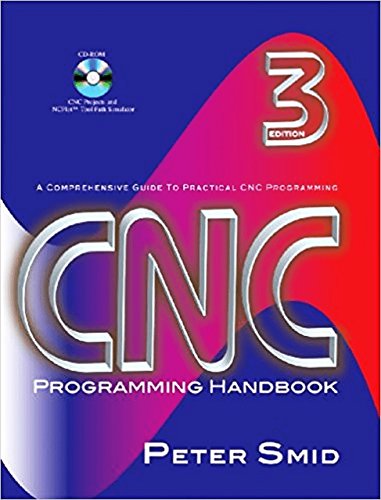
If it's the latter, then a really good book would be CNC Programming Handbook by Peter Smid. It covers damn near everything about CNC milling and turning, from machine kinematics to G-Code.
We've had this problem before. We switched over to a higher quality coolant (Blazer), but we have had two individuals that have still developed irritation. They use a barrier cream made by 3M and that seems to take care of the issue.
This is a link to amazon for a paperback version. It looks like there's a used one for sale for $50. You can see some sample pages to gauge the density and see if you think it would work for you. Let us know if this looks like a good solution and level.
have you considered just buying a big pack like this $10 for 200 pieces then you could just model them into your drawings and design around what you have on hand
Amazingly, Amazon. That's on the Canadian site, which means you might even find a better deal on the US site. AliExpress is always great for cheap machine tools too
Indeed: https://sites.google.com/site/0miker0/home
I'm working one of those right now actually. It's pretty cute and was not hard to assemble. Don't know where that guy got his plastic sheets so I used some MDF I found from an old shelf. Also I'm making a simple 6-transistor h-bridge stepper driver board to pair with an arduino instead of using a real CNC controller.
It used to be that a timing belt was a LOT cheaper than a lead rod but not anymore. The only time a belt is better is if you build a big machine larger than 500 mm. But then you would most likely want to go with a timing chain, again for less slippage and better reliability.
For motors generally I see Nema 17s and Nema 23s. Both are micro steppers. The 23 is usually for a larger machine. 17s are decent for desktop size machines.
Here's a link to get you started with the boards. Look around to find one ideally for you. https://www.aliexpress.com/item/4x-A4988-Stepper-Motor-Driver-with-Heat-Sink-CNC-Shield-Expansion-Board-for-Arduino-V3-Engraver/32660889229.html?
Definitely linuxCNC, it runs my mill, it's free and there is a lot to play with and learn. You can install it in a virtual machine like virtualbox so you don't need a separate computer.
This book is great. It talks about serious stuff, but it's not "for pros" and doesn't try to impress you. It's like being mentored by a really experienced (and kind of grumpy) older guy who is also a great teacher. Great stories, great lessons, about metalworking and about real life!
Not CNC specific, but a great read for anyone who wants to learn more of the craft of metalworking.
https://www.amazon.com/Metalworking-Sink-Swim-Machinists-Fabricators/dp/0831133627
Here's the closest thing I can find to what you have there, looks pretty identical. https://www.amazon.com/Mitutoyo-229-132-Depth-Micrometer-Counter/dp/B0006J445M
it depends on what plastic you buy. Many people mold things out of Kydex (an ABS/PVC blend) with just a heat gun or their oven. A vacuum pump will get you crisper details, but it might not be necessary for what you're doing (search for videos on vacuum forming or thermoforming).
Generally:
make a mold: it can be positive, or negative, or have both halves
heat a sheet of plastic (3mm kydex, for example). You could do this with a heat gun, or in an oven
drape the warm plastic over the mold and force it into the small places. Some people push on it, some use vacuum pressure, it depends on if you have surfaces you can scratch (the backside).
you may want this contoured part to be glued into a box. Many plastics will weld one of several ways: chemical, ultrasonic, or heat. So you might be able to assemble a pretty square shape (like the Amazon Fire) similar to the way people build acrylic fish tanks.
EDIT: like this? https://www.amazon.com/Amazon-Fire-TV-Streaming-Media-Player/dp/B00U3FPN4U
it's a rectangle... you can cut flat panels and glue them up
This is the one I use at work. Picked it up with HSMworks on the pc. Not sure if free version has bolt hole calculator but paid dose
https://play.google.com/store/apps/details?id=com.beta.fswizard_lite
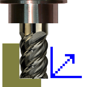
When cutting aluminum on a router, you have to rely on the chip to remove the heat from the cut zone. A single flute cutter, like this Onsrud O-flute gives a nice fat chip that will allow you to get a clean cut without using coolant. For this 1/4" bit, start off at 18,500 rpm on your spindle, 85 inches/min (2200 mm/min) on your feed rate and 3-4mm on your DOC.
Source: thousands of sheets of aluminum through my router.
(bit of a stream of consciousness coming up, but bear with me)
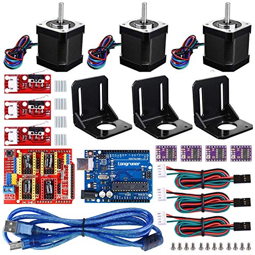
If you actually want the arms to appear stationary, you're definitely better off with steppers. They have maximum torque at stall (0 rpm) and unless you tell them to step, they'll just hold position forever. An arduino, a stepper driver (either shield or off alibaba, etc) two NEMA 17/23/34 motors (depending on your materials/counterbalancing) and 50-100 lines of code and you'll be good to go
something like this kit seems appropriate (in terms of parts list, not necessarily motor specs)
For control you'll definitely wan't an arduino, and for stuff like this I've had luck with the AccelStepper library
Ultimately though, your choice of materials for the arms is going to have the biggest impact on required motor size and resulting movement speed. With such long levers it doesn't take a lot of mass to cause a lot of torque
Another thing that reduce the weight on the arm would be moving the elbow joint's motor up the arm next to the first, and then actuating the elbow with a pulley/belt drive. Stepper motors are impressively heavy for their size, so the closer you can get them to the central hub, or off the rotating parts entirely, the better
Also note that motors aren't generally designed to much axial or radial load at all– you'll need to have the motors provide the drive for properly supported shafts
Here is a link of a rough idea with what we might do, we are definitely not going to use this part but how much we are cutting and the size of the material is pretty similar
I'm in the same boat as you. I can spend up to $1500 and it'll be my first mill... I do have a shop already though. The Shapeoko 2 looks great and the support is there but it's not the scale of CNC I'd want to use long term. I'm not sure how easily I could offload it once I outgrow it so I'm not sure I'll get one of those. The OX CNC can do 2'x4' if I'm reading correctly. The only problem is the parts are all out of stock.
It will depend on how big of a piece you're going to machine.
If you have long material you can use long metal bars on sides to push material down. Keep in mind that you have to make sure that your material will not bend around center in such setup.
If material is going to have holes in middle, you might be able to use those holes to hold your material in place.
Also, depending on material, you might be able to create your own jig to hold it in place. Most of the material can be thought of sheet form (unless you work with block or stone). You can use something like this: https://www.aliexpress.com/item/4pcs-CNC-Router-Fixture-Quick-Clamp-Chuck-Fixture-Plate-Engraving-Carving-Machine-Fastening-Platen-Woodwork-Aluminum/32618744450.html
Fusion360 is great, seconded.
If you're looking to do just 2d plotter stuff, there is a plugin built into Inkscape (which is open source and free) that will generate gcode: https://inkscape.org/en/
It's not super intuitive to use, but once you figure it out it isn't the worst.
For a really simple program, try Easel by Inventables: http://easel.inventables.com/
I do some plotter stuff, feel free to PM me with questions.
It sounds like you can do some sheet cuts for glasses. Plenty of CAM packages do that easily. Look at Vectric products and top of the line Aspire. Take a look at Cambam or Meshcam. Then if you are curious you can always see Mastercam or Alphacam for complex work.
If you are going Linux route see more links here : http://wiki.linuxcnc.org/cgi-bin/wiki.pl?Cam
Play around in this program : https://www.tinkercad.com/ Then you can export your model into different cam software.
You also need to understand that CAM software will generate g-code for specific machine/processor. For example there is open source GRBL, which supports big chunk of g-code standard commands. Then there are Mach3 or PlanetCNC controllers. So expect to understand differences if you are unsure which one you would like. Commercial machines will have their own flavors of G-code. Good thing is that most CAM packages will produce desired g-code when configured so.
Wow, a lot of taking the hard path here. https://www.freecadweb.org/ * Python is integrated in if you must take a programming approach * Reads all kinds of meshes, including STL * Has a CAM output module * Does Constructive Solid Geometry operations like subtraction
It'll take a little messing around to set up what you want, but you can script anything you can do in the UI
I took a look at your issue and I believe I can help you a bit. From the looks of it, you have a couple of things going on.
First - You shouldn't need a plugin to export DXF files from Illustrator. Go into Illustrator and at the top click on "File", scroll down till you see "Export...". When you click on Eport, you will see your file name, where you want to save it and a botton for which format you want to export as. Click on it and a long list will showup and DXF (AutoCAD Interchange File) will be near the top of the list.
Second - When you export a file from Illustrator, it will export EVERYTHING. Images, vectors that you have turned off, hidden vectors. I do mean everything. I think the green bounding box is from the image you live traced, plus you have multiple vectors stacked on top one another from when you made multiple attempts to make the vector.
Third - The vector of Georgia doesn't look like the state. I went and created a new file for you with your vectors and my vectors of Georgia on there. Your buddy should be able to cherry-pick which version he wants to use.
I tried to upload a DXF version but my drive is acting weird and won't let me. Here are a Ai and EPS file for you. https://drive.google.com/file/d/0B_iTNjKt0hQyWVViWVhxdmtXdk0/edit?usp=sharing
https://drive.google.com/file/d/0B_iTNjKt0hQySTFrNWczLTVOUVU/edit?usp=sharing
Illustrator can be overwhelming for someone thats new at it. If you need help, send me a message I will try my best to help out.
Okay, so.. Bad news is, I don't have a new cutter. Goodish news is, I re-ran the G-code for both of these shapes, and the machine ran on exactly the same path without any resistance, so I think that rules out a dull cutter.
G-code samples are here:
I'm certainly no expert, but the g-code kinda looks like what I was expecting. I'm curious to know if the experts see some issue there though! :)
I've also tried the following: * Slowing the feed speed - no change * Rebooting the computer - no change
This is correct
Fast deceleration requires a braking resistor. I use this one
A CO2 laser might be a better choice, but they are expensive small and have a lot of consumables. Have a look into Drag knives and see if they fit the bill. You could mount it on something lightweight like an Openbuilds Acro or an MPCNC
A 2.2kw spindle should be plenty. I had a 3.2kw on mine and never came close to reaching its limits. I use a 2.2kw now.
If you get an 80mm one with this style of mount, the holes line up perfectly to the back plate of the Z axis, and you don't need an adapter from Avid. Which is good because the adapters for holding spindles from Avid are terribly designed. Mine sits in the spare parts bin.
Ps. bonus of getting an 80mm 2.2kw, is that replacements are dirt cheap and super available if you need a backup. larger ones are harder to source and replace.
the outer most and inner most corners could use one of these CORNER CHISEL
~~not sure if that middle section is rounded over or a flat shelf... if flat it would work, if round... your looking at lots of sanding~~ looks like its round due to the shadow.. so no ideas there
Yes. That's correct. And you'd need a stepper driver, too.
Here's an example of a controller for a DC motor. I've never used it and you would need to verify that it's right for your application but it supports reversing and speed control in a professional looking package. That plus a gear motor and power supply would be all you need.
I've bought six of these (two sets) from Amazon and I've been very happy with them: https://smile.amazon.com/gp/product/B00C3NCA64/ref=oh_aui_search_detailpage?ie=UTF8&psc=1
I also bought these but haven't put them into service yet: https://smile.amazon.com/gp/product/B00QG1ZF48/ref=oh_aui_search_detailpage?ie=UTF8&psc=1
3 Axis GRBL 1.1f USB Port CNC Engraving Machine Control Board and GRBL Offline Controller Remote Hand Control for CNC Router Engraving Milling Mini DIY Engraving Machine CNC 1610/2418/3018/3018 PRO https://www.amazon.com/dp/B085L5S1F4/ref=cm_sw_r_cp_api_i_6sjHFbM0CGDHR
This is the Amazon link to the board I purchased.
I took apart my old xyz da Vinci to try and turn it into a cnc just as a fun project since I got a new 3d printer. I found the data sheet for the stepper motors here
http://www.nidec-servo.com/en/digital/pdf/KV42uni-en.pdf
When trying to jog the motors using the control board it seems to move them much more than the intended value. I measured with calipers that what the board said was 1mm was actually 9. The board uses the A4988 drivers which I thought would work with the motors since they seem to be nema 17.
Is this a simple software fix or is this board not going to work at all for this project. Thank you in advance
I cannot speak for them yet, but these are super cheap as tool holders go. I'm hoping they can handle most things. They appear well made. We'll see when they spin.
For most of my woodworking profile bits, I like to use Whiteside or Onsrud.
https://www.amazon.com/Whiteside-Router-Bits-1541-60-Degree/dp/B000AM18PE
I'd go 14k at 75ipm to start and adjust upwards if your machine can handle it. That's what I use for cherry. Go to slow and it will start to burn.
It has a 1500 watt water cooled spindle.
Here is a book I would use to make cool mechanisms when I was doing applications for 3D printers. http://www.amazon.com/507-Mechanical-Movements-Mechanisms-Devices/dp/0486443604/ref=pd_bxgy_14_img_y
There are a lot of pulleys and things you may not be able to use. But there are some real cool escapements. Check out the Geneva Escapements. Most of these are 2 axis but you can do bevel gears and such in 3 axis if you want to.
Knowing how to model in any CAD/CAM system is CRUCIAL when getting a job. Jigs, fixtures, heck just bounding boxes are things you will do every day.
Try to make something you can bring to an interview and have them play with.
Why not just use a VFD (Variable Frequency Drive Inverter) then you get soft start and speed control as well. Much cheaper, better efficiency, and much better control of motor giving longer life and better performance.
Yep just ordered some double sided tape for it my setup was clearly not enough for it.
Decrease the RPM speed. INCREASE the feed rate. Cut very shallow passes. The problem is hear build up that melts the acrylic. Every flute increases heat. That’s why you need to use a 0 flit if possible. Also, downcut is the worst decision because it drives the chips down and increases the heat and melting. Fast feed speed moves the bit to cooler plastic quicker.
When I cut extruded .093” acrylic I do it with slowest speed the router will go, about 120 IPM, and 3 passes with a cheap O flute upcut bit and have excellent luck
HQMaster 1/8 Shank CNC Router... https://www.amazon.com/dp/B074R9VXKQ?ref=ppx_pop_mob_ap_share
Here’s a helpful video
Not on a heavy router, but our 24R uses casters no problem. You'll just need more casters the larger/heavier you get, but it shouldn't be a problem at all.
Something like this is what you're looking for: https://www.amazon.com/Toolly-Leveling-Machine-Casters-Capacity/dp/B089GW4ZVP/
Those let you raise and lower the caster wheel so you can set the router on the solid legs (best for rigidity) or set it on the wheels for moving. They also let you level the router bed.
I found the small aluminium ones that came with my 3018 were useless and replaced them with more solid semiflexible ones as the other end is free floating.
May not be the best but this is what mine is running with at the moment.
https://www.amazon.co.uk/gp/product/B07D9JWNFC/ref=ppx_yo_dt_b_search_asin_title?ie=UTF8&psc=1
That compressor is nice, but way overkill for what you'll need just for the table. The 65 only requires 7.5 scfm @ 85 psi. I use a 5HP 2 stage I got on Amazon for my plasma cutter that uses a Hypertherm 45xp. It can do 15CFM at 100psi. It's a shame that it's nearly 40% higher than when I got it in 2020.
That compressor only has a 75% duty cycle, btw. Never been an issue for me, but then I'm not running full bore production either, so YMMV. I'd suggest the largest tank you can get to keep compressor cycles to the longest interval, or bite the bullet for continuous duty at at least 30% over your calculated needs. I'd recommend at least 2 water traps too. One at the main tap for the compressor and another feeding the hypertherm.
I stuck both the air compressor and dust collector for my workshop in a small separate room I built off the back of the garage. I can barely hear them run.
Which spindle did you put on that? It does not look familiar. Any idea of the runout?
I bought the Sain Smart Genmitsu 20K RPM 775L motor with full ball bearings because it sounded like the original 775 had precessing bearings it was so noisy. The new 775L also sounded like crap. Then I ran them with a 10 Amp Constant Current variable power supply. The motors were then very quiet and smooth. I think the PWM from the control board is rough on the motors. The original motor is full ball bearing so Comgrow did not cheap out on the motor. It is just a slower less powerful motor but perfectly fine for wood running at full voltage without PWM. Both the original 775 and 775L had the same run out inside the collet at about .0009 inch. I cannot measure any run out on the shaft so the problem is how the collett is attached.
This is the constant current power supply . PWM, Pulse Width Modulation is an attempt at constant current by spiking the voltage. It is very dirty. The better power supply is a clean and elegant way to provide it.
Tube has probably distorted from welding. Leave more material in the bore before welding. As said above
Quick fix to remove coat. Take a look here
I've upgraded a stock 3040 CNC to an air cooled 48vdc 500W brushless ER16 spindle a year or so ago, and it worked out great. There are a few considerations that may limit what modifications you are willing/able to make. Since the spindle was a much larger diameter, you must change the z-axis mount to accomodate the new spindle. On my machine, I had to literally saw off the existing mount in order to mount the new spindle. On top of that, I drilled new mounting holes and tapped them...all the while keeping everthing plumb and accurate. The motor alignment is critical...and generally not a project for inexperienced hobbyist.
However... if you can find an ER11 brushless 500-600W kit with the spindle the same diameter as your existing mount (~55mm) then that greatly simplifies the upgrade.
Something like this kit should work out fine.
They do make splitters for USB where the data and power capabilities are split. Generally they are marketed for cars so that people can use the data end so their phone can interface with Android Auto, and the charging end to plug into a more high-amperage power source.
You need paint that will stand up to the coolant exposure. Yes powder coating is best, but use a automotive grade paint/clear coat an you will get decent chemical resistance. Auto paint is tough and made to withstand the elements.
Get a quart or two of paint that is the color you want, then get a matching amount of clear coat.
They can be had on a-z.
Here's a link. There are others that cost less. The diamond tip will wear out. So you might want to have a replacement handy. Also sold on a-z.
Not to be an advertisement, but anyone interested in Fanuc macro programming should get and read Peter Smid's book amazon link...
Not the only book, but the best I know of.
I've used HOZLY ISO30 tool holders on my ATC router and they have worked pretty well. They appear to make BT30 holders too.
I've used HOZLY ISO30 tool holders on my ATC router and they have worked pretty well. They appear to make BT30 holders too.
Well currently I am eyeballing 4 of these for the discount https://www.ebay.com/itm/224459253315 and this set off amazon. https://www.amazon.com/Spring-Collet-Milling-Engraving-Machine/dp/B07MYS1HZ6/
Pull studs are gonna be the expensive part but im just gonna have to bite the bullet. Closest thing to a dynamite forum is thc section on CNCZone and they all have issues sourcing them as well.
Im just slightly worried about runout on china cheap tools. But Im doing this at home so I think thats all im gonna afford for now. Hopefully I will find some niche and fix that. I do have an in at a local gaming store.
No, it means Computer Numerical Control. This is a sub about programming machines to make precision cuts in wood and metal with machines like this one. https://www.amazon.com/Masuter-4040-Machine-Engraving-15-75x14-96/dp/B093LH9899
Sure. I made my own dust shoe from their design but will probably have to come up with a new design once I decide how I want to set up the tool changer.
I bought this compressor: https://www.amazon.com/dp/B00QFH5NCM mostly because it’s quieter and oil-free. Was tempted by a scroll compressor but it’s not much quieter and a lot more expensive.
https://www.eastwood.com/rockwood-1-2-npt-2-stage-air-filter-dryer-system.html is the filter and dryer I got, seems pretty nice but I haven’t been running it very long.
Also worth noting that the S30C with the avid VFD box only comes with a solenoid valve that switches air between the drawbar and case pressurization. If you want to control them independently I’d pick up a couple more solenoids from automationdirect (that’s what CNC Depot used in my box too) and hook them up.
I also bought VCarve Pro and it’s been fine, though I use Fusion for a lot of my more “3D” stuff
Wow, only $399.00! What a bargain, right?
Or, you can look at this one on Amazon that works great with a CNC Depot ATC spindle (or any spindle, really) and 4in dust system and is only 39 bucks.
You'd be better off with an industrial type supply. It will handle peaks better. China can be tricky, it's better to get something rated at twice or more what you need and you can be more confident it will last longer.
Check out these motion controls I mentioned in our other thread. These in theory could seriously beef up power and accuracy.
The dinky 1/4 belt drive on these machines is the single biggest limiting factor, a glaring weak point. Everything else reasonably well built.
GRBL is arduino based, so there's also really cheap USB controllers that can use a PC for the controller too. You'll likely need the discrete step motor drivers no matter which route you take.
Here's a little turnkey mill on Amazon for $125
https://www.amazon.com/dp/B08HRKLS6R/?ref=idea_lv_dp_
It's only about one step above mounting a spindle on your 3d printer but it's a cheap place to start learning.
I've built 2 of them this year and they will do aluminum, barely. The design has some flaws as well, easily fixed with 3d printed pla alignment plates.
Real machinists will tell you these are a joke, and they are, but the punchline is that they are adequate for a lot of folks.
In six months you'll have replaced 90% of the parts in the course of upgrading it to your specific needs, but you can do that gradually as you learn what you need and how to get there.
Shars Plate Demagnetizer Tool Dies Cutter, 6-1/2" x 4-1/2", 120V 202-1170 https://smile.amazon.com/dp/B081GG3X7V/ref=cm_sw_r_cp_apan_i_P1QJRHEFS0SX77Z7JW4B
I take that back, they are like $75 on Amazon.
Most of the operations can be done with this cutter, it won't take long. It's just some grooves.
https://www.amazon.com/Whiteside-Router-Bits-1572-Diameter/dp/B000ALY4EC
There's always Mitutoyo. Definitely worth the cost. Also they're still made in Japan, haven't been moved to China like most brands. Sorry for the Amazon link, I don't like Mitutoyo's website very much. https://www.amazon.com/Mitutoyo-500-196-30-Advanced-Measuring-Resolution/dp/B00IG46NL2/
The Marlin 3d printer firmware also works nicely for running a cnc.
Most 3d printer boards use a stepstick motor driver daughter board that can handle 1-2 amps at up to about 24v. For example, a RAMPS 1.4 board has 5 Stepstick sockets for 3 axis plus 2 extruders. To use a larger motor driver you can get a daughterboard that plugs into the Stepstick sockets and brings out the individual enable, direction, and step signals. They were about $2 each last time I ordered a set.
https://www.amazon.com/dp/B074FX5MHC/?
The Marlin firmware actually supports 9 axis, and none need to be configured as exteuders.
I'm currently building a custom cnc using a RAMPS board and screen configured for 6 axis, no extruders, one servo, one relay & spindle speed control. It uses the breakout boards mentioned above carrying the control signals to TB6600 stepper drivers rated 3.5a at 36v.
The sd card reader has a 8gb sd card with a host of canned routines that can be run from the menus on screen. Think key copying machine or dog tag engraver kiosk at the mall.
Linuxcnc is great, but if your controller budget is $20 a RAMPS board will work just fine.
It's definitely worth getting a lil set of collets, but you could also go with something like this https://www.amazon.com/dp/B091H2BGMR Haven't use it personally, but wood is pretty forgiving when it comes to bit selection
Bought on Amazon. ELUTENG 120mm Fan Filter 2 Pack IP40 Dustproof Blower Guard ABS Computer Ventilator Grill 12cm Fan Mesh Cover Tool-Free Fan Strainer Compatible for 120x120 Case Fan USB Cooling Fan https://www.amazon.com/dp/B075Q55ZNN/ref=cm_sw_r_cp_api_glt_i_A1E5QP7J17APVEE2GGDS?psc=1
These are what you probably want - "Abrasive Nylon Wheel Brush(320 400 600)"
https://www.amazon.com/Abrasive-Nylon-Woodwork-Polish-Grinder/dp/B0787ZPHKN
High grit won't remove your detail, but it gets the fuzz out of v-carves, etc.
Owners Bias Disclaimer
In terms of pure hardware and performance the vanilla 6040 cnc routers off Amazon or eBay like this are pretty hard to beat, and the base 3 axis versions can run as low as $1000 give or take.
Now there certainly are some trade offs for that low price:
No instruction manual/documentation
Little to no customer support.
May need to manually program vfd.
Stuck using outdated mach3 software or spend time and $ upgrading to different controller, GRBL, UCCNC, etc.
Lacks rigidity in some key areas, though still arguably better than other $1000 units.
Won’t get anywhere close to 10 um precision (100 um might be do able)
Sooo, not a turnkey solution, but once you get everything set up and the bugs ironed out they can be capable entry level machines that let you take on ambitious projects!
If you are dealing with stuff that small I would grab one of these
LABEAR Keyless Mini Drill Chuck Adapter ¼ Inch Hex Shank | 0 Inch to .039 Inch Capacity for Micro Drill Bits For Cordless Screwdrivers, Drills, and Power DIY Tools https://www.amazon.com/dp/B096VC6V98/ref=cm_sw_r_cp_api_glt_i_7KEVC7A4YEMYWMGPZB6F
For 10 bucks it’s a great option for crap like that.
Something like this is likely what you're looking for.
On top of this process, I use Marsh stencil ink instead of black paint. It dries quick. https://www.amazon.com/MARSH-Stencil-Spray-Black-weight/dp/B00DLD7JO8/ref=sr_1_2
well here is a rough estimate of what I might do, while I won't use this part the amount of holes drilled and type of material used will be similar to this
One possible way with scretching ink: https://www.youtube.com/watch?v=sNh0ubRcTYU
Another way with a cheap uv laser diode: http://hackaday.com/2016/03/03/etching-pcbs-with-a-3d-printer-2/
I tried to print abs directly on copper today but it does not really stick to it. I think a pen or the methods above are better.
The PrintNC is a rigid steel framed, linear rail + ball screw CNC that probably fits your needs. It uses printed parts mostly for drilling jigs and alignment but the major components are all metal on metal, it happily chews through aluminium at proper DOC and F&S
There is quite a few builds completed or in progress at the moment that you can see here
https://www.notion.so/Gallery-ec2d65f67879401fac79c2fd285c456a
There is also a very active Discord chat that is worth dropping in on
check out www.threedesign.store
(ob disc. my machine so a little biased, though I only will post a reply if I think the question asked is well suited to my machine)
Might I point out that you can get a brand new chinesium CNC on Amazon for about $120
Amazon - 24 PCS Hexagon Acrylic Gold Wall Mirror Sticker, Mirror Wall Decor, Mirror Self Adhesive Mirror Tiles Aesthetic for Bedroom Living Room(2.5"/Gold) https://www.amazon.com/dp/B08NCXVQYQ/ref=cm_sw_r_apan_glt_i_8JN84FSPYEWEXAYCSTCX?_encoding=UTF8&psc=1
Openbuilds is overpriced (and they're bunch of rat bastards, but that's another story).
A VERY basic cnc is $150ish on Amazon. I put one of these together this afternoon.
https://www.amazon.com/dp/B084265V72
It's barely enough to do aluminum, great for wood/plastic or just getting your feet wet.
I would like to have a special solder tip made out of turned brass. Something similar to this but with different dimensions (approx same width and inner diameter though).
If someone can make and mail me this, send me a private message. Thanks
Hi, I've tried using PathCAM for a pretty simple 2.5d object I'm trying to make, but it only seems to generate paths for cutting the object out, and not the inner cuts.
I've included a link to the STL file. Maybe I'm doing something really stupid. The object was designed in mm.
https://drive.google.com/file/d/0B0Ycaz7oEtPPRW81dzVNaTdaV0k/edit?usp=sharing
there are a lot of vids on youtubes and stuff, you just have to figure out what method you want to use, photo resist, direct print, etc
http://hackaday.com/2008/07/28/how-to-etch-a-single-sided-pcb/
yeah drilling for through hole parts or vias, which are harder to do at home, the easiest way is to use via rivets but they're not cheap and you need larger vias. otherwise its a whole process of filling in the vias and plating them, or soldering wires between the two layers
http://www.lpkfusa.com/Store/pages/productdetail.aspx?pid=147
single sided is a lot easier to do if possible.
Lots of people have built soundproof enclosures for CNC mills. Just look around.
eg. http://www.acousticalsurfaces.com/ http://hackaday.com/2014/09/28/sound-isolation-box-makes-living-room-based-cnc-routing-tolerable/
Speaking as someone who recently bought the same machine and the only 3rd party item i purchased was this dust cover that works amazingly. Also new bits would be nice as well so an amazon gift card would be beneficial to let him decide what bits/tools he could use.
I'm also on a well with very hard water. I got an rodi system off Amazon and it makes 5 gallons every 3 hours. Watch nyc cnc's video on it. Talk to your coolant rep but mine said no softened well water. I got this, the in line tds meter, and a canister filter. https://www.amazon.com/dp/B00204CQF6
If the software doesn't have direct support for pixel images you will need to auto-trace or re-draw the pixel image.
Auto-tracing is usually done in a vector editor:
https://inkscape.org/en/doc/tutorials/tracing/tutorial-tracing.html
and you'll want to learn vector drawing in a tool such as Adobe Illustrator, CorelDraw, or Serif's Affinity Designer (free options are Inkscape, Cenon on Mac OS X/Linux, or GraviT).
This is such a helpful list!
​
In your design software list from your previous post, I didn't find mention of Inkscape (primarily an illustration software) but it also can create SVG's that can be used to do 2D CNC designs. As far as I'm aware this one is also free and open source with a pretty dedicated fan base (which means some pretty handy user-created plug-ins).
Odd, the g-code files should be available for download by anyone. I redid the permissions just in case.
Here is the DXF.
Are the shafts you have larger than the side openings in the aluminum extrusions? I was considering a design a while back that used round rod in the slots, 60% of it protruding, top and bottom with guide wheels rolling on it. My plan was to epoxy it in place. Literally lay it into the slots, verify the position was straight, then inject epoxy along the joint on both sides.
Or, you could make your own fully supported linear rails... http://hackaday.com/2012/04/23/cheap-and-easy-linear-supported-rail/
1PPR isn't much better than cutting open loop. I'd recommend encoder with at least twice the resolution as you desired cut TPI, preferably more. High(ish) resolution optical encoders are cheap.
I picked up one of these air quality monitor kits because I found some research showing the sensor actually works for pm2.5
2.8" Digital Car PM2.5 Air Quality Detector Tester Meter AQI Home Gas Monitor https://smile.amazon.com/dp/B07DL1M46J/ref=cm_sw_r_cp_api_glt_fabc_PTCJ4AAPT8GWA779QND8
One thing to note is that this sensor reports pm1 and pm10 values but that is just an estimate based on pm2.5 measurements. That makes it less useful in the shop since it can’t detect larger particles (visible dust) in the air.
I suspect it works no better or worse than any of the other sub $100 detectors.
Just wire something like this on the hot line of the incoming 110V. The hot line will be the one that gives you 110V to ground.
Make sure you use a heavy gauge core 10Ga or better SO cord (or solid copper) to the wall and if you can you may want to skip a plug, remove the outlet and hardwire it straight to the wall. At 15A a 110V plug will get really hot even if it's rated for it.
Setting it up to test it and seeing what it actually draws will be important. Then you can decide how best to do it safely and not burn your house down.
I know it's been a while, but I've learned a little more since I bought those parts. You are right on about Vetco. I didn't realize that it was a storage auction. That's awesome. I was going back every few weeks because I wanted one of the 18" lead screws but the only one they had was in a bigger unit ($175 or so?) and I couldn't justify it. I asked if they would part it out and they said no. Thankfully they had quasi-disassembled it a month or so later and I got it for $75 with two Nema 23 steppers, a rotary solenoid, a cutting wheel, expensive-ish rollers, motor drivers, wiring, hall-effect end stops, and a bunch of 1/4" aluminum plate. I tested it out as-is when I got home and it was a kick-ass paper cutter until I took it apart.
I used some of the wiring and two NEMA 17's from one of my earlier Vetco finds from the same lot on my Shapeoko 2 and I'm working on integrating the endstops, but I think I have everything I would need to set up a super high-speed plotter or something. Maybe even a 3D printer? I don't have one yet and I'm not sure if I would have to sacrifice accuracy for the potential speed. I really need to figure out how to use the motor drivers. I think they are PIC based and my only micro controller experience so far is the Smoothieboard 5XC I have running the CNC machine, Arduino and a little bit of Raspberry Pi.
Have you done anything with the parts that you found?
it looks like this is the board it actually has inside https://www.aliexpress.com/item/Free-shipping-cnc-4-axis-3-5a-tb6560-stepper-motor-driver-board/32426895468.html?spm=2114.40010308.4.49.kt5Uyy
Overall great site, keep up the good work! BUT there is one thing I would like to point out: these JPEG artifacts are hurting my eyes. Images look nasty. Placing Your graphics in PNG format would be so much better. You can use PNGGauntlet to compress images. Best regards!
List of commercial options here: http://www.shapeoko.com/wiki/index.php/Commercial_Software --- Moment of Inspiration is the one which I'm most tempted by. http://moi3d.com/index.htm
For 3D CAD, the free / opensource options are really limited on Mac OS X, w/ most of them using X-window or running in a browser, or having restrictive licenses (YMMV).
I forget the exact prices but for an industrial use software it is a cheap option. But not cheap for an individual. I think it runs around $8000 per seat for the basic version and several hundred a year for maintenance fees. Depending on how computer savvy you are, you can always find and install cracked copies of solidworks online.
If you are a student, you can get the 1 year educational version for $100
I think, but not sure, that rhino3d is another good economical CAD software. http://www.rhino3d.com/
You could use python, but it would be like re-inventing the wheel. There are some libraries, but usually more trouble than it’s worth. I do have a few simple python scripts to help manage gcode (headers footers timings for toolpaths etc) but I would use something else to generate the actual code.
If you look up some examples, the “code” is basically just a list of coordinates in order. The machine just follows them step by step. Open Scadwould be the most analogous to a programming environment with modules and loops etc but most people design stuff in 3D using something like Fusion 360 then generate toolpaths from those models using other software (or different modules in the same software).
I’d recommend looking into either Solidworks or Autodesk Fusion 360. I’m using Fusion right now to design my molds. The downside is that Fusion is not as popular, and quite frankly, not as powerful. Here’s what I mean: Autodesk bought out other companies like Moldflow, but they have not integrated the software together, so you have separate software packages. Solidworks has everything in one package, and they even have training on injection molding part of the software. If it were me, I’d go Solidworks as it’s powerful in all the aspects you’ll need, not just mold design.
Blend the edges of the pic and use it as a displacement map on a 3d model in blender or something, export as STL to the shop. What looks like is happening there is that there's no grayscale transition so there's only up or down, you need gradation to make things smooth. Lotta ways to do this, if you feel like tossing me some cash I'd do it but hopefully that'll get you on a nice path or at least give ideas!
*https://www.blender.org/manual/modeling/modifiers/deform/displace.html
I'm not sure I completely understand your setup, but it sound like you have a computer setup and workflow that works for you currently. One option you might consider is remotely connecting and controlling your existing setup from overseas. e.g. remotedesktop.google.com . This does mean that the computer will have to be connected to the internet, but you can have your family turn on and off the network connection. Setup a web cam so you can also see what's going on with the machines so you can instruct.
​
However, the whole plan seems likely to run into trouble. Is there no one in your family willing to learn?
I have realized that the AI file I just posted has 4 paths because of how the design was set up. I have altered the file to just have 2 paths with one design shape. Which is here: https://drive.google.com/file/d/0BwNAmvdBwbtheUo0N2JJejFudkU/edit?usp=sharing
Hello sorry about your fusion troubles. OnShape is made by the former team that made solidworks. https://www.onshape.com/product-tour . Personally I would not convert anything. We work in both and its not really a bother. Its not like you have to buy metric tools for metric jobs to cut something. In some respects wood is easier but it does have its drawbacks, warping, strength, resilience. What exactly are you trying to develop? Also, if you have any other questions you can pm me or find me on my website.