
What are
/r/FreeCAD's
favorite Products & Services?
From 3.5 billion Reddit comments
The most popular Products mentioned in /r/FreeCAD:

The most popular Services mentioned in /r/FreeCAD:
FreeCAD
Liberapay
Inkscape
Filemail
Crowdin
CadQuery
Quixel Suite
Shutterstock
Onshape
nanoCAD
GitKraken
FileTransfer.io
LBRY
Blender
MakeHuman
The most popular reviews in /r/FreeCAD:
What you're describing is called the topological naming problem. There's a Google Summer of Code project open for this: https://www.freecadweb.org/wiki/Topological_Naming_Project and you can also find a lot of information by searching https://forum.freecadweb.org for "topological naming".
Essentially, when you make a sketch depend on a topological name, it's a very brittle dependency. If you have a cube, say, with faces Face1 through Face6, and you attach a sketch to a face, any operation which causes that face to change, e.g. filleting one of its edges, will break that dependency. Also, the ordering of faces can change, so that what was once your correct attachment to Face1 now points at a different actual face on the object.
Besides the topological naming project, this is also being addressed in 0.17 by allowing for things like datum planes, which can parametrically defined. So for example if you have a sketch on the XY plane and you then pad it to Pad.Length, you can make a datum plane which is parallel to XY plane at a Z-position of Z=Pad.Length. Thus this plane parametrically represents a sort of "top".
For now, your best bet involves trying to minimize the number of sketches attached to geometry.
No no ... please don't miss understand me. Funding for freecad as a whole absolutely helps the project. There is this place where funding is evenly split between the major coding contributors https://liberapay.com/FreeCAD . From personal experience I can tell that receiving even small amounts of "Thank you" money is nice and helps with morale off contributing basically for free to an open source project.
My statement of having a centralised foundation to manage donations could be detrimental is just that. A personal opinion(more of a fear) and I might be awfully wrong about that. For example I see blender foundation managing quite well funding from big tech so anything is possible.
If the trapezoid should change its size:
- Make two sketches on either side and use this tool. Make the hole and the cutout afterwards.
If it should has the same size over its whole length:
- Just extrude the trapezoid from the side and make the hole and cutout afterwards or
- Cut the outsides of the trapezoid beginning from the side.
BACK-UP YOUR 0.16.67.xx FILE BEFORE OPENING IN 0.17.xxxxx! MIGRATION TO 0.17.xxxxx MAY CAUSE PROBLEMS.
Release notes: https://www.freecadweb.org/wiki/index.php?title=Release_notes_0.17
Hey Bud, I learned a trick yesterday, that reminded me of this question you asked and may be what you are looking for.
You can change the 'environment' texture map. When you right click on the object and change the material type a reflective one, it reflects the environment. but by default this is just plain white.
You can change the environment texture map, by clicking on the 'view' in the top menu, ticking the 'environment' box and choosing an environment texture map.
You get very realistic looking chromes and metals if you choose a blurred faded out texture, similar to something like so: https://www.shutterstock.com/image-vector/colorful-cover-design-template-abstract-blurred-650284294
Hopefully this is what you are looking for.
I have exactly this problem. I am on Windows 7, and have been using FreeCAD for a couple of weeks. It has been good until today (always on the the latest stable version, 0.19-24291 downloaded from https://www.freecadweb.org/downloads.php).
I disabled my security software. I tried opening and exporting old files from before the problem. I moved everything in AppData\Roaming\FreeCAD to a new directory. I tried with security off and the FreeCAD configuration files restored. All I have accomplished is that now instead of not being able to export a file, I can't even past opening the file chooser. Before I can select a FreeCAD file to open it closes and FreeCAD crashes.
About:
OS: Windows 7 Version 6.1 (Build 7601: SP 1)
Word size of OS: 64-bit
Word size of FreeCAD: 64-bit
Version: 0.19.24291 (Git)
Build type: Release
Branch: releases/FreeCAD-0-19
Hash: 7b5e18a0759de778b74d3a5c17eba9cb815035ac
Python version: 3.8.6+
Qt version: 5.15.2
Coin version: 4.0.1
OCC version: 7.5.0
Locale: English/United States (en_US)
I have not tried the AppImage version. Is there some reason to do so, then the main site takes me to an "exe" type installer?
After reinstalling from a fresh download of the file, the symptoms are slightly different. I can open the file selection dialog, but as soon as I double-click a file FreeCAD crashes.
I'll try a development release, just to see if it helps. I just hope this doesn't go on all night. I had finally learned FreeCAD well enough to get some useful things done, even though I'm still a beginner.
I'm using 0.17 here. When I create the angle constraint, it opens a dialog box called "Insert angle" and it has two text boxes - Angle, and Name. On the right end of the Angle text box, to the left of the up/down arrows, is the f(x) circle.
There's some documentation on it here. Per that article, you can also pull it up by typing "=" into the Angle box.
As others have said, if you want to use FreeCAD for this, you'll be using the FEM workbench, which defaults to using Calculix to do the calculations (with some other solvers available/in progress).
There are two main ways to model buckling in FEA: eigenmode (aka linear) and nonlinear. Eigenmode buckling is good for getting working solutions, but it's limited to a fully linear model (no contacts, no plasticity). I don't think FreeCAD exposes eigenmode buckling in the GUI, but I'm pretty sure it can be done directly with Calculix. Nonlinear buckling is much more flexible, but requires a lot more work to stabilize the model and get a converged solution (particularly as the geometry "snaps" into its buckled shape). You just need to enable nonlinear geometry in your model to start experimenting with nonlinear buckling; I'm pretty sure FreeCAD gives that option somewhere, but I don't recall where. I've only just started playing with the FEM workbench myself.
Buckling simulation is an interest of mine, so feel free to ask for help.
Quote from the article:
> In this work, MBDyn 1.6.1 (a free, open source multi body dynamics simulation software developed at Politecnico di Milano University, Italy; (see: https://www.mbdyn.org/)) in combination with FreeCAD 0.16 (a free and open source CAD modeler developed by a non for profit Free Software community (see: https://www.freecadweb.org/ )) are used.
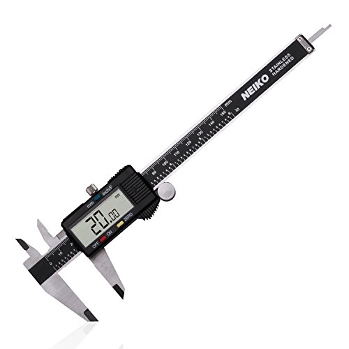
I'm interested in using it for drilling the holes in a sheet of brass to make a stencil like it's shown in this video. I bought mine from here.
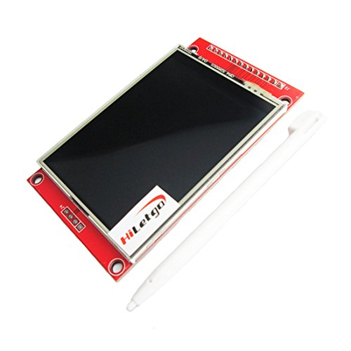
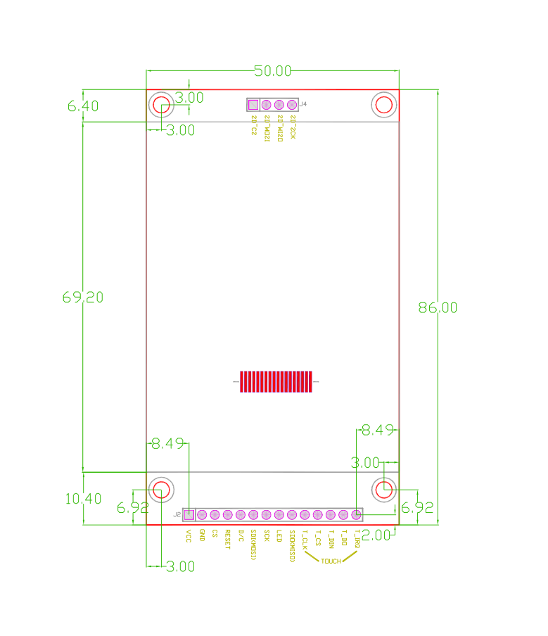
I am working on a project which uses this display and needed an enclosure. Using some enginerring drawings I found for a similar display I had an enclosure designed and 3d printed within just a couple hours. Fun stuff!
cadquery is similar to OpenSCAD, just in python and using a different CAD core.
Basically, instead of using a GUI to draw and construct your models, you use code to describe them. Since I am a software developer, it was easy for me to get into and now I get better results quicker with cadquery than with FreeCAD, so I will stick to it.
https://cadquery.readthedocs.io/en/latest/quickstart.html#quickstart
Topological naming, and User Interface. That is basically it.
TPN fix is coming with 0.20 thanks to Realthunder's work.
User Interface is so hard in large scale open source applications because as u/HopefulAtTimes mentioned, there's very little "structure" to development. No design committee or overseeing figure or visionary for this application. It's just a dozen people in their spare time being paid not-nearly-enough to create this software that requires a lot of niche knowledge.
No one is there to make the call of "We're changing the workflow for this tool, it's better now, get over it," because it's a community project and things have to be agreed upon without ruffling feathers. And there will always be someone who doesn't agree, because "change is bad!" So instead of just making an educated design decision and users adapting to changes a little bit at a time, there's yet another probably-unnecessary preference buried in a menu or hidden behind a keyboard shortcut. Or, even worse, development on something doesn't even start because it's not a "good fit" with the way FreeCAD works right now and no one would agree to make that change, even if it is for the better.
I am not trying to disparage FreeCAD or its community or development team. This is probably the worst part of any open source project of this complexity: without a leader always looking at the big picture (and sometimes, allocating resources), it becomes a jumbled mess.
I would love for FreeCAD to be the next Blender; it needs at least one UI/UX expert, and a leader who would let that person make changes for the better. And, you know, millions of dollars a year to pay everyone to actually do this would be great: go donate!! https://liberapay.com/FreeCAD
windows 10 enterprise
freecad version 0.19.3 from here : https://www.freecadweb.org/downloads.php
started having this issue on .2, reinstall didn't help, disabling firewall also did nothing.
Do you mean the letters "R" and "K"?
I don't know what your specific issue is, but Inkscape is free and typically works pretty well with FreeCAD.
Also you could look into Draft > ShapeStrings if you just need letters in a particular font converted to FreeCAD shapes.
Okay, I think I have the shape drawn, now.
When I switch to the Part Workbench and try to Extrude my sketch, if I select the checkbox for "Create solid" I get an error of "Wire is not closed."
I've tried "Close Shape" in the Sketch workbench, but that throws a redundant constraint alert, and deleting any of the constraints causes the part to change shape.
I'm messing with things now, and I'm pretty sure I don't understand how constraints work. I want the belt path to be 1.86mm wide for most of the length (after the opening). So I set a Distance constraint between the endpoints of my two arcs. Which means I can move the other lines around them and get a mangled pretzel, as long as those two points are at the same distance... Not making a valid belt path. I haven't figured out how to set a constraint that keeps the two arcs the same distance apart, which is what I was trying for. Or keeping two lines parallel and the same distance apart.
Here's what I have so far. https://www.filemail.com/d/sryygarjehndsfv
I didn't realize that I couldn't post text in a media post. I'm pretty new to Reddit.
I tried to make an account on the FreeCAD forum, and wasn't able to, so now I'm here.
Here's a link to download what I already have in fcstd. I'd really like instructions, instead of just a finished part, so I can learn how to do this for myself next time.
​
https://www.filemail.com/d/snojtdoaqpfjqjg
​
Thank you!
I'm assuming these panels are steel sheet? If you can replace these panels with acrylic sheet, you could use a CO2 laser cutter to make your design, which would be much cheaper and easier. If steel sheet, keep in mind other subtractive manufacturing techniques like YAG/fiber laser and plasma cutting, I don't know how well a traditional CNC mill handles sheet metal...
Draft workbench is powerful but I rarely ever use it, this 2D design that you're doing really calls for Sketcher workbench in my opinion. Sketcher is a suuuper handy tool once you get used to it.
Definitely talk to the fab shop and see what file formats they will take. If you end up needing to export DXFs, you may want to do (export as flattened svg > open in Inkscape > save as DXF). FreeCAD's DXF exporter was buggy the last time I checked.
Very weird. Does the Draft dropdown menu at the top give you anything? I would try with the v0.19 nightly build instead.
Inkscape is great for text. You can write with the text tool, then convert to path with Path > Object to Path, then save as svg. You can import the svg in FreeCAD using Open > SVG as geometry. This should bring in all of the paths as objects in the tree, with the Inkscape dimensions matching the FreeCAD dimensions. Then you can select one of the paths in the tree, and go to Part Design > Create Body. This will make a new body with the path as the BaseFeature. Now you could Part Design > Pad the BaseFeature, and use the Pad to Part > Cut into your die.
Here is a screenshot that I made using this method.
Also once you get the Draft workbench working, you can use the path objects that you import from Inkscape, and Draft Modification > Draft to Sketch tool to get a sketch that you can use to Pad / Pocket / etc.
What version on FreeCAD you have? In the latest version, now current stable version downloadable at our main page : https://www.freecadweb.org/downloads.php
Above at the left corner you can find a green cube with an arrow clicking on it. Well. This is the function you search for select all the edges of an item without always click Ctrl+select on the edges of the solid. This item works in the "Part workbench". Or If this don't fit the answer at your question you can check the video who diamened show to you in the comment section below. Or write a help letter at the FreeCAD Forum at our main page. You can find it above the site by clicking "Community" . Have fun with FreeCAD ;) .
I think using datum planes/points is the level up in workflow you're looking for: https://www.freecadweb.org/wiki/Sandbox:PartDesign_Bearingholder_Tutorial_I
If you installed from the Ubuntu 18.04 repository then you got FreeCAD 0.16 which is really out of date.
Read the instructions on https://www.freecadweb.org/wiki/Install_on_Unix carefully to add the freecad-stable PPA and install/update FreeCAD again. This will get you FreeCAD 0.18. It may or may not work better but at least you will have the current version.
Yes, I think you’ll have to. A body is defined as a single contiguous solid. Your two parts aren’t connected.
Look here for info on that restriction: https://www.freecadweb.org/wiki/PartDesign_Body .
You’ll need a shape binder to create the second sketch relative to the first. https://www.freecadweb.org/wiki/PartDesign_ShapeBinder .
I've looked at your file. If you want to learn to analyse problems like this in FreeCAD, first order of business is to look at the dependency graph for your document: menu Tools / Dependency graph...
(Actually, first install GraphViz as mentioned here or the above will not work.)
You will see there is a circular dependency in your design. "Pad" depends on "Final" which depends on "Cut" which depends on "Pad" again. Such a circular dependency prevents FreeCAD from recomputing your document.
I'm not exactly sure what happened in what order, but it appears that you are mixing modeling techniques from both Part and Part Design workbenches.
This solves your problem for now: delete both the "Fillet" and the "Final" object. Your design will be instantly recalculated or you can click the Recompute button on the toolbar (or hit Ctrl+R). Then if you want to apply a fillet, do it with the tool in the Part workbench and apply it to the "Cut" object, not to the "Body" or "Base" objects.
And BTW you could have created your "Base" by adding a cuboid or extruding a sketch in the Part workbench, and you would never have needed to switch to Part Design.
I sometimes tell people to consider the Part and Part Design workbenches as essentially two different CAD programs in one package. They both have their own ways of doing things. I'm sure in time they will become more unified but we're not exactly there yet. You certainly can use them together in a single project or design but then you need to understand them both very clearly. You can make your life easier for now by sticking with just one of them. My vote is for Part Design because it is the most flexible and powerful of the two.
>for the Z offset value of your datum plane click the f(x) button and select
>
>Pad.Height
I recently encountered the feature editing best practices page, and have been wondering how to do exactly this. Thanks.
https://www.freecadweb.org/wiki/Feature_editing#Advice_for_creating_stable_models
As someone else who's pretty new to the program, I'm going to advise that you learn to save your work often. FreeCAD has its fair share of crashes.
Also I recommend getting used to using variables as soon as you can. Keeping everything parametric makes it a lot easier when you go to make changes.
It's compelx. So the quick answer, No, they are not part of core. But you can install both A2+ and Assembly4 via the FreeCAD Addon Manager very quickly. I'm not certain about Assembly3.
well, sure. these are great tutorials. but you add something to it rather than reposting them here. you could try adding English subtitles. or make videos yourself. assembly 3 and 4 are there. make some demos. here you can learn more ways to help FreeCAD:
Sorry for the short answer but what you want now that you've completed your model is the TechDraw workbench which is used to produce plans you can give to someone to (re)create your model.
Yes, this can all be configured. First of all, this all takes place in Edit->Preferences->TechDraw. Note, these TechDraw preferences will only show up if you have first opened the TechDraw workbench once.
Now that you are in this Preferences dialog, everything you want to configure will be the TechDraw Dimensions tab. have a look at the following page for more information if my above explanation wan't enough: https://www.freecadweb.org/wiki/TechDraw_Preferences/en
First, for the line width, while in the TechDraw Dimensions tab, in the decorations part of this page you will see "Line Group Name", change the item in the box to anything on this page: https://www.freecadweb.org/wiki/TechDraw_LineGroup. For example, I think the default value in the box I'm talking about is "FC 0.70mm" so if you want the smallest pre-defined width as listed on that page I linked, change the item in box to "FC 0.25mm". Obviously, don't use quotes.
For the dot/vertex size, change Vertex Scale to something smaller. This is in the same tab in the same part of the page. I think the default value for the vertex scale is 3.00mm, That is, if you are using FreeCAD units of mm.
I don't use datum planes and shape binders, so I can't speak to their effectiveness as workarounds, but my workflow works pretty well. I map all of my sketches to faces, NEVER use external geometry, make heavy use of the local origin of the sketch, and keep almost all of my parameters (lengths, diameters, pad thicknesses) as named variables in the Spreadsheet workbench (as described in the Writing properties section of this page).
Sometimes if the object to whose face I've mapped my sketch changes its number of faces, the internal names of its faces get shuffled and my model breaks. However, the fix is usually simple, I just need to map the broken sketch to the appropriate face on the object again.
The basic tutorials show you how to create sketches on faces, but that can be a very bad idea.
Learn to use datums and shapebinders to avoid your work getting frustratingly scrambled if you try to change something:
This tutorial shows how to center a hole in a face. https://www.freecadweb.org/wiki/Creating_a_simple_part_with_PartDesign
I went to look up the order of selection for Part Cut but it turns out part cut doesn't accept a mesh as an input. Instead you should probably use the Mesh Design workbench which has a tool "Cuts mesh with selected polygon." Never knew about it personally, gonna try it on something eventually.
Drawing WB is deprecated. TechDraw WB is what OP is looking for I believe.
TechDraw Forum is also useful.
I think this is what you're looking for.
​
https://www.freecadweb.org/wiki/Spreadsheet_Workbench
​
​
​
If that doesn't work, I would try making a script to convert your known point list to an IGS file with points and then import the IGS file into CAD.
NonUniformRationalBezierSplines
looks interesting
.
did not see a link to download and install
..
Is this the "nurbs" listed here :
https://www.freecadweb.org/wiki/External_workbenches
I just stick it in git (like I do everything else). I don't feel much need for an integrated VCS plug-in. Git kraken works well for me.
I write fairly decent commit messages to avoid having to try to read diffs.
I think the issue is not so much VCS, but diffs. Thing is: How are you going to make those humanly readable? Even in code this can be challenging and that is text based media; this is visual media.
It could be helpful for FreeCAD to support an uncompressed storage method so git and the associated diff tools can make text comparisons. Then leave it up to git to handle the compression generically. This should be super easy to implement as zipping is probably 1 line of code that can simply be skipped with a setting.