
What are
/r/OpenPV's
favorite Products & Services?
From 3.5 billion Reddit comments
The most popular Products mentioned in /r/OpenPV:

![Galaxy Note 10 Privacy Tempered Glass Anti-Spy Screen Protector [3D Curved] [Case Friendly] [9H Hardness] for Samsung Galaxy Note 1](https://m.media-amazon.com/images/I/51WntzJAw4L._SL500_.jpg)


The most popular Services mentioned in /r/OpenPV:
Google Drive
Circuit JS
HackADay
Thingiverse
Onshape
Poll Everywhere
Amazon
Alibaba.com
GearBest
DealExtreme
IGTV
TinyPic
Imgur
OpenJSCAD.org
Alibre
The most popular reviews in /r/OpenPV:
Yeah, I love that app.
You can even export a link to a circuit. Check out this. Drag the Voltage slider to see the LEDs change.
Sure^^ the switch is here: https://www.amazon.com/dp/B01N7HCJ7S?ref=ppx_pop_mob_ap_share
As for the coils, it's a 26g kanthal w/ 30g Nichrome clapton, wrapped with 0.8x0.1mm Kanthal ribbon. Reads .20 ohm and the flavor is holy warm and dense ^ ^
Which board..? If DNA, appropriate wire gauges will be listed in the data sheet.
But generally, 16-12 gauge for the high current stuff & 24-20 gauge for low current stuff.
Unless you have a specific reason for lead free solder, leaded will flow much better: https://www.amazon.com/gp/product/B0149K4JTY/
Would recommend some additional flux also: https://www.amazon.com/gp/product/B00425FUW2/ (clean up with isopropyl alcohol & qtips - even thought it says "no clean")
The closer you get to the threshold, the higher RDS(on) becomes. This is the resistance of the MOSFET when conducing. Times it by the amperage^2 and you have the heat the MOSFET will have to dissipate: anything over 2w for a TO-220 package without a heatsink will damage or destroy it.
I made this Excel sheet to help me figure amp draw and dissapation, although the RDS(on) values in there at the moment are for a TI CSD18502KCS, you can just replace them with the ones for the 3034.
HAH Figured it out. So it is Alibre. Come to find out, they got bought by 3DSystems and don't offer that trial anymore, however, if you could find a older copy of it somewhere, I believe its a free license.
Edit: So there is a Download Page Link on this page. But it takes you to a 404 Error.
I found this circuit simulator great for both learning electronics and trying out ideas before committing to buying parts to try it for real: http://www.falstad.com/circuit/
It's a Java applet, nothing to install, and you can even share circuits through clipboard text or even a URL.
You can find different colors and shapes!
And thanks a lot, trying to get this box thing down!
Here's the ones I like best https://www.amazon.com/dp/B00M50SEYC/ref=cm_sw_r_awd_jNN5ub1ES5RNR It's super easy, you get 3 position side switch on/off/on it'll have 3 tabs to solder to. Outside tabs are 1 straight from the voltage to the 510 and 1 from the battery terminal positive. The middle tab is for the positive to the volt meter. The negative of the volt meter too common ground. One way you'll read the combined voltage of the battery sled, this will show constant on the display. The other direction shows voltage at the atty. This only shows while you're firing for obvious reasons.
https://instagram.com/p/0YrmmfSn4x/?taken-by=albertrahm
Sorry it's the only one I took and I really don't want to open the whole thing back up. Just pop out the old 510, you can use the old wire if you really want, solder it into the 510's positive pin, press in the new 510, a little epoxy on the lip of it and you're gold!
I think it's your standard cheap-o crap. You'll hate the iron on day one as you feel the cheapness in your hand. Then you'll be disappointed that the heat doesn't transfer because the tip rattles in the socket no matter how much you tighten it down.
Oh no. You tightened it too much and now the EXTREMELY NARROW AND LAUGHABLY SMALL ceramic element inside has cracked.
Or... You could get a nice Hakko and keep it for a generation.
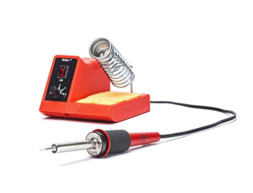
Or... If the Hakko is out of your price range you can get the same Weller half the world uses and will also last you a generation.
This is the connectior you need for the lipo balance leads. You are also going to need XT60 male & female connectors for the main leads off the pack. But honestly if you are going that far you might as well buy a new enclosure from Analog box mods or one of the dozen other sellers and just put the board in a new enclosure. (Edit* yes you might as well get a new lipo too, whatever enclosure you decide on pick a lipo to fit)
I guess I am more so wondering where I can find out what specs I need for the resistor & LED firing button (looking at this style button, plan to buy from digikey or mouser if I can find it with the proper specs). Would the necessary specs for parts be included in the evolve spec sheet for the board?
Be sure to check out some of the cool battery holders on http://thingiverse.com for inspiration. There are some quite cool ideas on there. especially the 3d printed spring designs such as http://www.thingiverse.com/thing:456900
I whipped this up this week and it fits in a 1590A box well but you have to modify the lid to make it all fit together. I'm going to try another version that leaves room for the lip on the 1590 lid.
Where are you mounting the SX350 in a 1590B? On the side? or on the back?
3d model: http://www.thingiverse.com/thing:421448
I use something similar to this sMAKN 0.28" Mini 2 Wire Dc Voltmeter 2.5~30v Yellow Digital Display Voltmeter Gauge LED Voltage Detector https://www.amazon.com/dp/B00D76DV0U/ref=cm_sw_r_udp_awd_J4UZtb0EYKCZVXXK
I don't use this manufacturer, they suck... But a .28" is the smallest that I can find.
I would not recommend this in general (why do you need to permanently attach a battery to a circuit?), but you would want a capacitative discharge welder to be safe. The design itself involves very little heat transfer, which makes it the de facto means to weld a battery cell to something.
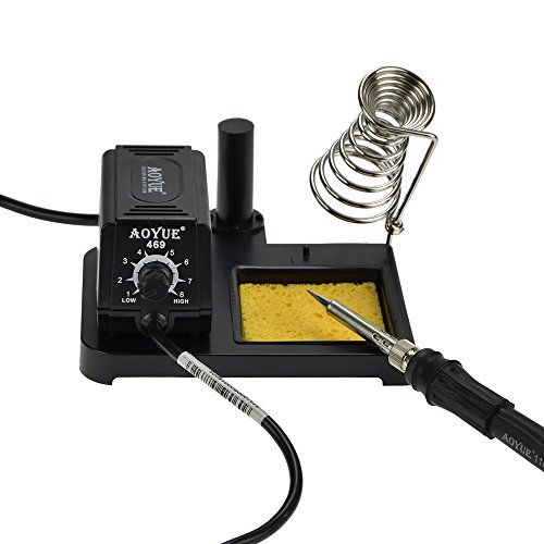
I hear you on that. If it was years ago, I'd say buy weller but I use those daily and the quality of tips has drastically gone down, replaced 6 last year. That cost more than the aoyue cost for the entire station. This article I had read gave me semi confidence in the brand even though I'd never heard of them. http://hackaday.com/2009/02/20/tools-aoyue-968-3-in-1-soldering-and-rework-station/ When I bought this, I bought my dad the weller station like at work. 6 months my station is on its original tip, his has needed a new iron and 2 tips.
Keystone and mpd seem to be the go to but I found a cheap Chinese one that's listed as a little smaller dimensionally and might help me cram everything into a 1590g
You'll have to replace the wire leads with thicker gauge tho
This one also has springs which may cause more voltage drop, I'm going to measure it when my keystone and this cheap one come in and I'll update
too wide? this one is smaller in width but longer in length
http://www.fasttech.com/products/0/10005926/1585501-tp4056-1a-li-ion-battery-charging-module
http://www.dx.com/p/tp4056-1a-li-ion-battery-charging-module-blue-4v-8v-215797
You could mount one of these in between your box and your 510. It would take a little modification but it would be kinda cool, I think. I suppose you could also just use it how it's meat to be used and put it between your atty and your 510 but where's the fun in that?
Look into Floris box mods, he sells these sexah little delrin box enclosures. Several DNA options on his site, here is the 40/60. https://www.ecwid.com/store/boxmod/#!/DNA40/c/19885131/offset=0&sort=nameAsc
Really like the idea. Actually I'm building a 3D printer (a "Kossel Mini" - a delta printer) currently. I got interested in 3D printing because I wanted to create a mod for a SX350 chip, looked into shapeways for printing stainless steel but the price... besides reprap is really interesting for many thing.
I think 3D printing needs a web based tool that can parameterize things. I know thingyverse has something like that, but they are stealing all designs and try to patent them, that is why many boycott thingyverse (there are alternatives or github).
There is OpenSCAD that lets you "program" engineering designs, but even better would be http://openjscad.org that is web gl based and allows parameters. So you could make one design and change the battery size between 18650, 18500 etc. Change edges from sharp to rounded or flat corners. Change size for your button or change the diameter for your tank or 510 connector inset.
Ideally a 3D printed mod should take advantage of the unique possibilities of the additive manufacturing process. Allow easy parameterization of the surface with custom logo, text or 3D patterns. Maybe add reliefs from greyscale images / heightmaps as ornaments. Or import 3D meshes and plaster them on the sides.
As soon as I get my printer working I want to play around with that. A parameterizable open source project that incorporates different designs and styles would be awesome!
PS: For people looking to 3D print stuff http://3dhubs.com might help you find people in your vicinity who have a printer and offer printing services (probably much cheaper than shapeways).
I thought the links would be able to be copy and pasted.
Apparently they are from here: https://www.polleverywhere.com/multiple_choice_polls/zP2ft9yJ0GLii3v but not from original link to poll...
It looks like I need to rethink Q1 as I had wrongly assumed it would provide both benefits. Thanks for the kind words. I use gEDA for circuit design. Definitely the easiest program I've worked with that allows custom components. I believe I found some Windows binaries floating around if you wanted to try it out on something other than Linux.
You're right about S1. I'm going to have to move it somewhere else to preserve the reverse polarity protection. However I'm getting answers about how an N-FET won't work at all. The only reason I started with an N-FET was because I was messing with it in this simulator: falstad.com/circuit. The N-FET is providing reverse polarity protection it seems in this simulation. Let me know what you think.
I think that was the main concern with putting the main switch on the on/off pin. You mentioned it draws current even when sleeping? If I were to use an N-FET solely as a current-carrying switch, would this remove the current draw in sleep?
Thanks so much for your reply. Straight from the horse's mouth on a lot of these. After doing more research, you're absolutely correct that S1 nullifies the reverse polarity protection of the MOSFET. Taking the switch out, however, and wiring the N-FET a bit differently than the P-FET, it seems to provide reverse polarity protection: falstad.com/circuit simulation. If I were to move the switch somewhere else and keep the N-FET for reverse polarity protection, is there any functional difference between using a P-FET or N-FET? Maybe wiring is easier?
Your explanations about everything else helped a lot - especially your switch explanation. Thank you!
Yes you bought something wrong. For the same money you get this https://www.amazon.com/908D-Soldering-194%E2%84%89-896%E2%84%89-Adjustable-Temperature/dp/B08CRMYH7V and I can recommend it as I bought it and it is the best you can get for under 100 Bucks. Just one thing: Follow the advice given already and throw out the solder which comes in the kit and get the best lead solder available, you will save yourself a lot of pain by doing this. Kester #44 should be on Amazon too. And get some "no clean" flux as paste in a syringe then you are fixed.
This thing heats up in seconds and it reduces temperature to 100!C when you put it in the holder, it also has a thin flexible silicone cord for the price it is a dream.
You can buy the soldering iron alone without the rest for about 10 bucks as I did, you don´t really need the rest but the solder and flux are essential.
The temperature on the box is just for orientation you go and find what suits you what will be around 280+ C° for soldering leaded solder, and 350+ C° unsoldering.
Dont forget to clean and tin the tip before you put it away for storage and it will hold for a long time due to automatic temperature reduction.
This is automotive paint, but is very durable and a lot of PC case modders use it.
Here's one:
http://www.amazon.com/dp/B00BZQ2LJG/
Here's /u/david4500's MOSFET schematic: https://i.imgur.com/x7AUu5A.jpg
The voltmeters are pretty simple, you can test them by putting a wire on each end of a battery. Extending that concept you just work it into the voltage line so that positive is on the positive side, and negative on the negative. There are also 3-wire voltmeters on amazon. If you get one of those, just tie the red and white wires together.
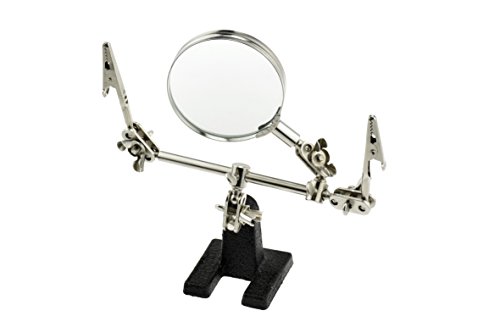
Thanks! I started my build this weekend and didn't get that far. I never have to do anything precise with my hands and I didn't realize how unsteady/shaky my hands are. I got a Helping Hands coming in from Amazon that should help, and I'm going to take another stab at my build this weekend.
I have Power Out and Ground Out from the top of board done, I have the battery sled done, and I have the bridge from B- to G and the bridge from B+ to 2,3,4 done. I just need to attach the sled to B+ and B-, and attach the Tap wire to 1 and I can test it out. If everything works, I just need to connect the 510 and fire switch, then epoxy it all into the AlpineTech GXL box I have.
It all sounds easy, so hopefully when my helping hands come in it will be easy.
I used to use cf polycarbonate.. you need a good printer that can reach high-ish temps and all-metal hotend (prusa mk3s fits the bill), but it's a great material to work with. Because of the carbon filling, it doesn't warp much (polycarbonate is typically a nightmare material work with), and the finish and texture are very clean looking. Also it's a tough material and has great heat resistance.
​
This is the one i typically made my mods out of: https://www.amazon.com/PRILINE-Polycarbonate-Filament-Dimensional-Accuracy/dp/B074DS3986/ref=sr_1_3?crid=26LTRI7KP8Y8D&dchild=1&keywords=carbon+fiber+polycarbonate+filament+1.75mm&qid=1597167934&sprefix=carbon+fiber+polycarbonate%2Caps%2C217&sr=8-3
So, I'm going to offer my 2 cents on this one, It's a not a cleaning issue. OP, you're NOT going to solder that with a 30W iron, and you'll have a problem soldering it with a $200 80W hakko iron too.
There's too much metal in that area to heat it to the 300C that you need to solder, The only way you're going to be able to solder that is to use a high power soldering gun such as this https://www.amazon.com/Weller-D650-Industrial-Soldering-Gun/dp/B000JEGEC0 you can probably find one at a harbor freight that'll do the job too for half that price. you'll want 150W or more.
you could either try to flow into the previous joint, if there's still solder left on the brass ring, or get some sandpaper and sand it and try to flow solder onto the brass ring, then try to solder the wire to it.
​
edit; I'd actually reassemble it and put it on the vape shelf.. I just noticed the inductor inside the device is badly damaged too, it might work if you fix it, but it won't live a long life.
In the case of a sound solution, I'd guess you'd use a minimum decibel to fire it off (high enough it doesn't just go off in your pocket). In the case of measuring decibels, I'd test it a lot before I'd trust it at all. There are also pressure sensors like this that exist, it'd just be a matter of safely incorporating it (probably through an airflow channel).
Kinda related but for anyone looking for a battery that is a 4s and fits the alpinetech B box for the 250c. This is one of the biggest I could find (please inform if I’m wrong, bigger the better!). I failed to realize it did not come with a 3s lipo connection. Happy building!
Venom 30C 4S 1400mAh 14.8V LiPo Drone Battery with Universal 2.0 Plug (XT60/Deans/EC3) https://www.amazon.com/dp/B0199R5RCA/ref=cm_sw_r_cp_api_wwUSAbD5KR23M
> On-off slide switch - https://www.mouser.com/ProductDetail/612-EG1271A
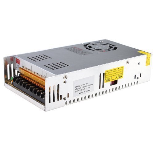
>The particular supply used is 60W 12V 5A - https://www.amazon.com/gp/product/B013HHN1I0/
Awesome! Thanks for the info. If I get some extra cash, I'd love to commission a build. :)
I wouldn't use that PSU. however I'll buy the most expensive PSU that's within budget, just on principle and experience of losing more than I care to admit to cheap powersupplies. If you needed 12V for a fan, lights, or similar loads I'd definitely get this power supply.
On another note.. it doesn't say if that unit is even listed, UL listing might not matter to you (it should). here's a listed PSU of the same rating. https://www.amazon.com/dp/B007K2H0GI/ref=psdc_1161760_t3_B00D7CWSCG notice the price difference, and remember that old saying about what you pay for.
TL;DR if you like gambling buy that PSU. I personally wouldn't based on the lack of UL listing alone. Everything else you need to know was pretty much covered.
This one will probably be easier to tell from since one of the pics is a schematic.
I guess my question was more aimed at asking whether or not it would be a good idea to use one of these for a vapestation. It's not a PC power supply, it's sort of an all-purpose thing, but the question is whether or not it's meant to handle short burst heavy loads rather than constant low load like from a CCTV or radio.
I'd vinyl wrap the sections of the tank you want. Or find a sticker that is what you desire. A sicker or vinyl will eventually come off. You could also heat shrink wrap it if you really want something that won't come off, but you'd need to find the right size wrap. You could sandblast it to get a frosted look. Paint could work, but since glass is so smooth it is likely to chip off rather quickly.
I'd probably order a few stickers or vinyl and just replace them when they fall off.
Edit: heat shrink like this https://www.amazon.com/dp/B01IHDYW00 it's 25mm diameter and shrinks when heated. It can be a pain to get off if you ever want to.
I use a cheap Chinese one off amazon . This one Its 60 watt with adjustable temp and came with a kit. Does the job and was cheap. You will also need some no clean solder flux paste and some solder. I wasn't sure if the solder the kit came with was lead free or not ( lead free isn't as good) so I bought my own solder at a hardware store. It's not the greatest set up but it's done me good so far. I am not the most experienced modder on here though. I have only built 2 boxes so far but both turned out well. Just to warn you its hella addictive. I have parts to make like 5 or 6 more boxes already. The hardest part is just getting everything to fit inside the enclosure nice and neatlty. The enclosures look roomy until your trimming down your wiring to finish up soldering. I would say start with something easier so you don't fuck up am expensive board but my first box was an intelligent PWM board and was glad I started on something a bit more technical. I'm finishing up a dual battery squonk with only a mosfet and it's a piece of cake now.
As for your DNA 200. I would have to research myself. I am a YiHi fan. I have 2 SX Mini G Classes so I have never looked into the price of boards. I will look around. So far I found a 200 for $56 on dripp3d.com
> Can you recommend an inexpensive soldering iron? I don't wanna a super cheap one but, I probably won't use it enough to justify $100.
Have a look at this one and check out the reviews
https://www.amazon.com/X-Tronic-3020-XTS-Digital-Display-Soldering/dp/B01DGZFSNE/
Forstner bits seems to be for wood. I'd want to use tooling meant to be used with metal such as an end mill.
From a quick search:
you're good man. But I know I'll need help.. I work two jobs, and try to have a social life, Oh, I don't know code/really don't have the time to learn. not that I wouldn't want to, there's just not enough time to learn enough to do everything even if I never slept.
I'd rather no-one know what exactly my evil plan is and what I'm doing until it's in their hands.
Open-source jake converter is not happening. it's no-ones business how I drive the individual stages the circuit, and nobody has any business changing the maximum or minimum values of anything related to, it'd be outright stupid to do so, and no offense intended. if you want to edit those, Skim through thousands of pages of datasheets while you're reading this book https://www.amazon.com/Electronic-Communication-Robert-L-Shrader/dp/0070571384 and Electronic Fundamentals for Technicians and https://www.amazon.com/Transistor-Handbook-Cletus-J-Kaiser/dp/0962852570 then spend hours on digikey looking for components that are electrically and psychically fit for the application, and read those datasheets as well when you do. I didn't do all of this in two weeks, but I've read those at some point, or most of, and I've used them for various formulas many times over. Anyone on here is more than welcome to do the same, they'll have the same opinion that it's idiotic for a complete open-source driver.
I got some of this to try out. I wanted the syringe type instead of a tub and brush.
Here is the vacuum pump I use with a pressure gauge and a big pickle jar. It works. https://www.amazon.com/ZENY-Single-Stage-Economy-Conditioner-Refrigerant/dp/B012CFTYX4/ref=sr_1_4?ie=UTF8&qid=1501206918&sr=8-4&keywords=vacuum+pump
its not hard. youll need a drill for the through hole and a 7/8" counterbore. Just take small steps and measure to make sure you dont over shoot the depth.
https://www.amazon.com/7-8-Interchangeable-Pilot-Counterbore/dp/B008RYUQLY
Like this one (but you will need the correct pilot for the though hole)
I could put this behind say a plastic trigger for a game controller with a spring http://www.allelectronics.com/item/mpb-143/soft-touch-tactile-pushbutton-spst/1.html
And I love how these are designed but i cant seem to find one like it for DC. https://www.amazon.com/Uxcell-a13112000ux0329-Trigger-Switch-Piece/dp/B00HGAM5UU
Yea Qg is super high in high current mosfets (typically), thou the NXP ones are considerably lower and thus more efficient for a PWM circuit. If you want you can get a decentish usb oscilloscope. https://www.amazon.com/Owon-VDS1022I-USB-Oscilloscope-Isolation/dp/B00HC4UP52/ If you get an oscilloscope that's USB ensure that it's isolated, that will protect your laptop from death.
Really depends how deep you want to slink down the rabbit hole lol.
Funny you mentioned AOYUE, i was literally looking at this when I got the notification for your comment. Any good? It says ESD safe
If you want to make an unregulated mod, check out all the links here about using a mosfet: https://www.reddit.com/r/OpenPV/wiki/index
The flux you are currently using is corrosive. You should use some meant to be used with electronics instead of pipes.
For example: https://www.amazon.com/MG-Chemicals-Clean-Paste-Syringe/dp/B00425FUW2/
Even thought it says "no clean", clean with isopropyl alcohol or acetone afterwards.
This right here is amazing for as cheap as it is. I am sure that if you punch in the model number you will pull up one for the UK.
https://www.amazon.com/gp/product/B00MCVCHJM/ref=oh_aui_search_detailpage?ie=UTF8&psc=1
Ninja edit: nvm found it for you.
I really like this stuff: https://www.amazon.com/gp/product/B003HGHQ8S/ It has that fancy vinyl coating and all around good quality, pre-tinned wire.
I also order thinner stuff from allelectronics.com, including heat shrink tubing.
This is what I'm using, still working on my technique. The POS terminal on the sled has 4 wires soldered to it, so it doesnt look so good :P
P.S. It also doesn't help I stayed up all night building this.
One more for you; Looking at this on Amazon, any thoughts? Also, where I have a seam between edges from doing the outside and inside, will I want to buff or anything or is this going to be like concrete and slow and steady wins the race?
This is what I have, grabbed it as straw material originally.
White SiliconeTubing, 3/16"ID, 1/4"OD, 1/32" Wall, 10' Length https://www.amazon.com/dp/B000FN1FLA/
It doesn't fit like a tip, too small, but it is thin enough to stretch around quite a few tips. Sorry I don't have a caliper on me right now.
I purchased this to fill in the gaps, hopefully it will help
https://www.amazon.com/gp/product/B00EZH3IOY/ref=od_aui_detailpages02?ie=UTF8&psc=1
I bought this enclosure (its a monster) to go with a fat daddy 510
https://www.amazon.com/gp/product/B00HKISEJ4/ref=od_aui_detailpages00?ie=UTF8&psc=1
I guess I should watch the DNA install video and see what goes where and the sizes I will need. Im also totally clueless as to how I will attach the screen and board but I assume the video will explain that.
Yep, this size is fairly common. If it was make before break it would have awful disaster potential. I'd still prefer more headroom than 30A if I was to do it, and definitely if I was selling them.
I'm currently building an unregulated 1591BBK with a ModMeter, p channel FET, and this lipo (though not bought on Amazon, there's a hobby RC shop not far from where I live). The width on that box is just barely big enough to accommodate a ModMeter built into the side. I doubt that a G box would be big enough, without building it into the door / back, though I don't have measurements in front of me to back that.
Biggest issue I'm running into is wire management. I'm doing ok as long as I have short leads on my wires, but as soon as my Turnigy 90C 7.4v hardpack gets shipped (assuming it ever comes off of backorder, thank you HobbyKing), There will be about half as much room in the box to build with. I'm also not liking running a 20C pack; I liked the extra wriggle room that a 90C pack offered, so I'm only building down to 0.5Ω, but sadly I killed my hardpack by over-discharging it. I don't trust it to be the same rating if I try to "recover" it, last thing I need is a lipo blowing up in my face, so in the garbage it goes.
That.... that is not the job of a simple mosfet. It's also beyond my abilities so i can't explain the design process to you either.
Let's consider the hypothetical situation. We have an irlb3034 with a Vgs of 10V, our power supply has infinate current capability with no drop, and everything is connected with lossless conductors.
So when our mosfet is turned on it will have a Rds(on) of 1.7mOhms. I = E / R, so I = 8.4 / 0.0017, I = 4941.18A. But a mosfet is merely a switch, the load is what you want to switch and that dictates the current sunk through a n-channel mosfet. With PWM you're switching it on an off quickly giving you an average voltage, but a lot of factors come into play (mosfet dynamic characteristics) and i don't have the time to explain that all out.
Switching supplies are entirely different animals though, inductors are involved, diodes as well, physics as well. That's all beyond my skill set when it comes to rolling my own SMPS from scratch.
There are some books on it, however they tend to assume you already know a lot or have a formal education in electroncs. That and it'd coost you probably about 400 dollars for two books on the subject if you were to buy them new instead of rent them or check em out from the library.
Sorry i couldn't be of more help. And yes Vgs of 4.5V > is for switching instead of amplifying.
You'd be looking for books such as: http://www.amazon.com/Power-Electronics-Converters-Applications-Design/dp/0471226939/
http://www.amazon.com/Power-Electronics-Basics-Principles-Applications/dp/1482298791/
Along with a good background in general electronics and design.
ideally i'd like to be able to mimic my Sigelei 100w and utilitze the batteries I have. 2x 18650's rated for 35A, 2500mAh in series.
Thought I rarely use it past 60w it's nice to have.
These are the parts I've bought thus far to start learning about everything I'd need to make this.
I buy these kits and go through many of the sizes.
4" Length Heat Shrink KIT - 176 Pieces - 2:1 Shrink Ratio - Size Range: 1/16" to 3/8" - Color: Rainbow https://www.amazon.com/dp/B00PHL4788/ref=cm_sw_r_other_awd_1BtHwb0D7J0BH
You can find the same battery on Amazon. Here. I don't suggest buying from Hobby King because of the shipping costs, I was merely showing the battery I use. I got mine from Amazon.
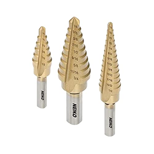
Use a step bit
Mark the size you want to drill into (these are into US std measurements, so you have to convert to the closest size down.) Then drill to the desired measurement. The hole should be slightly smaller. Use a deburring tool to size it up.
You would need something like This. 6-15v variable DC power supply with a 22 Amp limit.
The DNA200 you can buy at Modcrate.myshopify.com
The box isn't currently available but is on ebay sometimes. just search alpinetech enclosure.
Faceplate is here, the screws to use are in the PDF link in the description. I just traced the pattern and cut it as I needed to. Faceplate is secured with epoxy: https://www.shapeways.com/product/2SDPD4J3Q/dna200-faceplate-with-screen-holder-and-buttons?li=user-profile&optionId=57361418
This has been my preferred brand lately: UL1015 16awg Wire
It comes in different gauges and colors, obviously. The insulation is very high temp so it won't melt too easily while doing the battery sled connections or otherwise. The wire is also pre-tinned which makes soldering easier. The 22awg wire has pretty thick insulation on it though, just as a warning.
I use the ones /u/amdcursed linked when I need a DPDT. These particular ones are
Wrap the outside with black shrink so you don't seep epoxy into them when you glue them in.
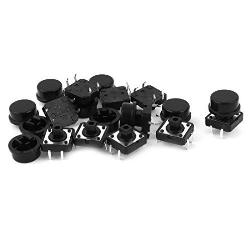
>Alternatively, if you know of any 12mm, very small, recessed momentary switch, please let me know. Thank!
Consider a 12 x 12mm tact with 10mm cap
Such as this: http://www.amazon.com/10pcs-Momentary-Tactile-Button-Switch/dp/B0087ZF6E0
I grabbed this set from amazon, it's on sale through may and is a pretty good deal imo:
http://smile.amazon.com/gp/product/B0035XHWNW/ref=oh_aui_detailpage_o01_s00?ie=UTF8&psc=1
Titanium pilot points, I have had any issues with walking and it chews through the aluminum!
I bought the mosfet from Amazon (http://www.amazon.com/gp/product/B00HKHW9UU/ref=oh_aui_detailpage_o01_s00?ie=UTF8&psc=1). You said that my mosfet isn't suitable and I need one that is >= 100A but mine is rated for 195A. Just wondering if you misread it or something. I have another box that uses the same mosfet (things seem to be going good). If you didn't misread I'm going to have to take that one apart and replace it.
Thanks for the great links and info. Those mosfets are 3x cheaper than the ones I bought on amazon.
edit: Yeah, now that I look at my mosfet's specs, the RDS is subpar at 1.4 milliohms but the VGS threshold is at 1V.
I solder for a living on a weller station with a professional iron. Recently I purchased this Aoyue 937+ www.amazon.com/dp/B000I30QBW/ref=cm_sw_r_awd_LQN8ub0H6DYJQ. I had no idea what I was going to get and I couldn't be happier. I love it, it's thermo regulation on small projects such as box mods is spot on. Another bonus, it accepts hakko tips.
Enclosure is painted "pewter vein" from http://www.pedalpartsplus.com/mm5/merchant.mvc?Screen=CTGY&Store_Code=PPP&Category_Code=ENCCS page 6
Fire switch http://www.amazon.com/gp/product/B008420SSA/ref=oh_aui_detailpage_o02_s00?ie=UTF8&psc=1
I think you could attach a switch similar to this one to the tube. Then it can be activated by pushing it with your lips.
It would be similar to this setup. The switch is labeled 8 and is activated by the upper lip.
You can use this to replace the switch in a mod as long as it is used to control a circuit board in the mod.
If you are going to use it in a unregulated mod (one in which the switch is the only thing between the battery and the 510 connector) then you should look into MOSFET builds. The MOSFET acts as the switch between the battery and the 510 connector, and it is controlled the by the lip switch. This makes it so the full power doesn't have to go to the lip switch and though the long length of wire.
I had the PSU from this laying around and I've been using it while I wait for my 30amp PSU to arrive.
You want something like this: http://www.amazon.com/Soldering-Accessory-Solder-Tweezers-Desoldering/dp/B00PQYCZPI/
Flood the pin with low temp solder to dilute the stuff from the factory. Then alternate working the pin with the picks and tweezers, and vacuuming the solder off with the pump.
Cleanup excess solder with the wick.
Get a soldering helping hands. Makes things so much easier.
For solder I would just go to RadioShack and get the thinnest stuff they have.
Edit - it's probably all they'll have, but make sure you get rosin core. Lead free or leaded is up to you.
Hinged sphere enclosure? A Pokeball might be your best bet. I have a few of these on my shelf back in my folks place that I've been thinking about modding forever.
http://www.amazon.com/Pokemon-Gold-Plated-Trading-Limited-Edition/dp/B002GUJO1I
I have a file saved with a grid of all the parts I've used. I just copy/pasted those into a new drawing and added the visual dimensions.
I think I got the tp4056 board here:
http://www.fasttech.com/product/1453504-tp4056-1a-li-ion-battery-charging-module or
I would imagine the dimensions are similar aside from the port
i kind of feel terrible after a long soldering session so came up with this.
before I was using one of these..
You can do the same thing with this with an output side adapter similar to mine.
Think I used the second smallest of these countersink bits
http://www.amazon.com/IIT-25410-Counter-Sinks-5-Piece/dp/B001GMRD10/
The reviews mentioning that the bits are dull are accurate. Some force is required to use them.
A six flute countersink would be a better option.
http://www.amazon.com/s/ref=nb_sb_noss?url=search-alias%3Daps&field-keywords=6+flute+countersink
Some voltmeters come with a bezel.
Others are 3d Printed
Be prepared to wait a couple weeks for anything from Shapeways
http://www.amazon.com/gp/product/B00ENFBXQS/ref=oh_aui_detailpage_o00_s01?ie=UTF8&psc=1
I bought 2 of these... But it seems they have updated to a newer model. Mine are flatter and longer.
I'm going to create an adapter to use PC PSUs out of a male 24pin ATX connector. It'll have all the bells and whistles.