
What are
/r/diypedals'
favorite Products & Services?
From 3.5 billion Reddit comments
The most popular Products mentioned in /r/diypedals:

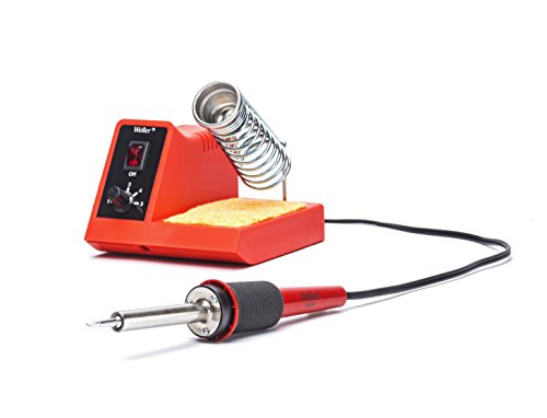
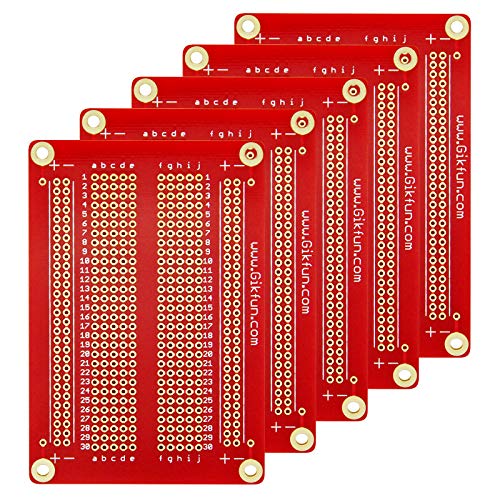
![Soldering Iron Kit - Soldering Iron 60 W Adjustable Temperature, Solder Wire, Tweezers, Soldering Iron Stand, Soldering Iron Tips Set, Desoldering Pump, Solder Wick, Heatshrink Tubes [110 V, US Plug]](https://m.media-amazon.com/images/I/51a8NCGvcpL._SL500_.jpg)


The most popular Services mentioned in /r/diypedals:
Circuit JS
Pexels
HackADay
LTspice
DuckDuckGo
CircuitLab
Inkscape
Gofile.io
PortAudio
Fritzing
Microsoft OneDrive
Wayback Machine
Google Drive
HTTrack
ChucK
The most popular Android Apps mentioned in /r/diypedals:

The most popular VPNs mentioned in /r/diypedals:
The most popular reviews in /r/diypedals:
Hate to be that guy but you should invest in a multimeter with a diode tester.
I can also suggest getting a MEGA328 based component tester. It's a godsend!
https://www.amazon.com/Mega328-Transistor-Resistor-Capacitor-Mosfet/dp/B01H6QKVOU/
Microcap12 (recently discontinued and made free) is probably one of the better options for installing a SPICE simulator and hitting the ground running for designing the type of analog circuits that pedals use. http://www.spectrum-soft.com/index.shtm
I got you.
HFS (R) 1 Pair 123 Blocks 1-2-3... https://www.amazon.com/dp/B016PFPMPG?ref=ppx_pop_mob_ap_share
You gotta stack em. It helps to have two. To get right up on the edges specifically, you can turn them vertically(single block) and move them as you go a couple of punches at a time. This is only necessary on the very bottom or top of a 125B. They don’t quite fit perfectly in between the end and inset material for the machine screws. Get an old case you fucked up and practice to get the hit power correct.
I drew lines with a ruler with a pen to have a line to go on. Then i wiped them off with alcohol before i did the sharpie.
For the black stuff…..
Im sure there’s a better way but i did it quick and cheap. I filled them in with as much precision as a sharpie offers. I wiped the excess off with alcohol, let it dry then hit it with acrylic clear. Two stout coats. Done.
Use a spring loaded center punch. It keeps your drill bit from walking off. I don't build pedals but I am a fabricator and they are perfect for getting a good hole everytime.
I use them when using the 9v jack that has an internal nut because it makes assembly and disassembly much easier and quicker. I also usually build everything, put in the enclosure and play it for a while before I decide what art/finish I'm going to put on the enclosure. Also to . And sure I like the pedal enough to take the time to do some art and epoxy on the enclosure. So the connector makes it a breeze to take in and out.
I was taught to bend the legs around the shank of a small screw driver. This will help protect the components and aslo prevent kinking the legs. They make a tool for this. https://www.amazon.com/Production-Devices-801-Forming-Resistors/dp/B07XYDGSD9/ref=mp_s_a_1_5?dchild=1&keywords=lead+forming+tool&qid=1623104483&sprefix=lead+formi&sr=8-5
So close, you could have done a search and found these instead
<https://www.amazon.com/Letool®30-1-25mm-Female-Connector-Cables/dp/B013JRWCBU/ref=sr_1_57_sspa>
:-)
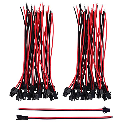
I’ve been on this quest to make a fully modular dual-overdrive pedal system. I am in the middle of prototyping all the circuits, and last week I replaced the boards in my first prototype with new revisions. I thought I’d try these nice JST connectors I got on Amazon to make the whole thing fully modular.
The idea was good in theory but they ended up taking up a crazy amount of room! I might try a smaller JST variant but fitting these all in was tight. You can’t even see it but there’s another one crammed down above the top board under the jacks.
In a less cramped build they might work well. Here’s the link if anyone’s interested. The silicone coated wire was nice to work with.
First, make sure the template prints at 100% — my computer defaults to “fit to page” and then prints a letter-size page at 96%.
I cover the whole enclosure in 2 layers of painters tape (to protect against scratches) and then tape the template over that. I use an old school manual center punch (not the spring-loaded kind) to make a pilot mark, then I drill starting with a very narrow bit and working my way up to the appropriate size for each hole. Anything past about 5/16” I use a step bit. I use a hand drill for this — don’t have a drill press. It takes patience but if you go slow you can get it accurate enough
One like this: CUI Inc SDI50-12-U-P5 SDI50-U Series 50 W 90 to 264 Vac 12 Vdc Output Level VI Desktop Power Supply - 1 item(s) https://www.amazon.com/dp/B073RPBBBM/ref=cm_sw_r_cp_api_glt_fabc_0NGZ52MDENWDHDG6XBMR
That’s not the exact model. I used a 24 v output with barrel jack 2.5 mm centre pin.
Except I ordered centre positive - need to get the center negative
You can safely delete everything starting with the /ref. Its all just tracking information so that Google knows who is connected to you through clicking that link.
https://www.amazon.co.uk/STANLEY-STHT0-51310-Fiberglass-Curved-Hammer/dp/B071JS9JZ4/
See!
https://duckduckgo.com/?q=digitech+bad+monkey+mods
Sit down and list your component set. Then go through the links brought up by the above (I see several that look promising), looking for a match with the parts list.
If you don't find it... I've used this quite a bit with good success. There are a few other similar tools out there
https://www.fontsquirrel.com/matcherator
Edit, for those curious but not enough to check it out: You upload an image and it picks out the text (you correct it if it guesses letters wrong), then it searches for similar fonts.
http://hackaday.com/2011/01/20/lego-wah-wah-pedal/
is only thing that springs immediately to mind :p
may be check out ebay for pedals to mod - game controllers, sewing machines? if you can not mount a pot may be consider a battery powered led (which would last for years?) and ldr combo? good luck.
I cant speak to the electronics, but:
>How can i design a drilling template, what software is good for that, or where is a place where i can look for a template that suits what i'm making
Microsoft Inkscape is what you want.
It's a free vector-based drawing software. The interface is ass, but you can even do a "virtual build" with layers at life size.
Adobe Illustrator is a better choice, but it's pricey.
Creating a drilling template should be pretty easy.
You should even be able to output an acceptable file if you want to send it to a CNC machine.
Apart from the other relevent suggestions offered by other posters here, download LTspice, a free program to simluate electronic circuits. You can find many examples of LTspice circuits for FX pedals via google and the Yahoo LTspice group, and many tutorials via google/youtube as well.
There are many online places offering PCB boards and/or FX pedal kits, including everything you need to assemble a pedal (PC, components, and build guides).
I'm gonna be a dickhead and say that ltspice exists for a reason.
The same dickhead would punch it into ltspice if he could read the values so you know what to do.
So I have some unhappy news for you. It's not going to work. Unless you build another circuit to make it possible. It states right on the page for the breakout board that "This PCB is for use with Buffered Bypass PCBs, no onboard buffer is included...Compatible with most buffered-bypass PedalPCB designs"... unfortunately, the Daydream is not a buffered-bypass design, so that board won't do a thing.
Now, like I said above, you could build a little buffer circuit and stick it in so that it would work pretty easily - but at the same time, note that even a well designed buffered-bypass will add to the noise floor when the effect is powered on or off.
I hope that's helpful.
They sell these on Amazon. They're great for being able to plug into power before boxing up and then being able to quick disconnect without having to cut the wires. They're great. (30 Pairs) https://www.amazon.com/dp/B0879F3XCC/ref=cm_sw_r_cp_api_glt_fabc_GGQSQ53MNS83ED03SAQM?_encoding=UTF8&psc=1
A steel block underneath is essential otherwise the top of the case will dip. I use two of these steel blocks stacked although I need to get another set just to make it easier. A good hard whack is key but I’ve also found the straighter the strike the more even the letter will be. If I don’t have the stamp as close to 90 degrees as possible I’ll only get a partial stamp. I have two sizes of these letter I got from Harbor Freight which are good and cheap but not as good as the set I’ve gotten from the craft store. Edit: you can do a second strike but it’s pretty hard to get it lined up in the groove you already hit. Not impossible but difficult.
A friend picked up this kit and it seems to be a pretty good starting place. Seems to be about the same price as placing a Tayda order in terms of the per resistor cost and would save the time of putting the order together.
Kester #44-flux 63/37 alloy 0.031" is hands-down the best I've used. That #44-formula flux precleans the surfaces to be joined, especially if you aim the tip of your solder so that it's pointing into the joint between surfaces as it melts, because then the flux spits right into the joint as it boils. Of course, there are limits -- if leads are corroded, heavily oxidized or visibly tarnished, you should scrub them first with a piece of flattened braid (from a piece of coax?) or Scotchbrite, so the flux and solder can get purchase.
63/37 is a better alloy for quick soldering for electronics than 60/40, especially for beginners. That "eutectic" alloy doesn't have a long "paste" period in its cooling where the lead is solidifying but the tin is still molten, so it's less likely to form "cold" solder joints due to being disturbed while cooling. If you're scrimping on fixturizing your assembly setup (to hold everything immobile), that can make a difference as to whether you'll need to reheat a joint to get it to conduct right.
0.031" is a good size for through-hole work. 0.025" is good too, a little more precise but you use it up a little faster too, and it's more costly on the sites I checked. 0.020" or 0.015" are more for SMD touchups and hybrids. If you're breaking out the wide-tipped iron or soldering gun to do heavy work (like PL-259 connectors or grounding straps), you'll need a thicker solder, of course, otherwise you'll use up your 0.031" too quickly. It'll work, it'll just be wasteful.
The above is an Amazon link. Mouser carries Kester too, at a higher price. I expect that all the big distributors do too, but the stuff lasts years (I recently bought a 1-lb spool, looking towards the end of the spool I bought in the 80's), so I haven't looked there in quite awhile.
Get an engraving bit. Those skinny flat end mills are easily broken. I broke one by dropping it 4” taking it out of the container.
Something like one of these: https://www.amazon.com/Degree-Double-Headed-Carbide-Engraving/dp/B005BOQ14Y
If your tip works fine, as yours appears to, id not worry about it. Oxidation elsewhere is probably protective, even.
For the tip itself I use this stuff. Works AMAZINGLY well. Oxidation literally bubbles off in seconds, leaving a perfectly tinned tip.
I am a big fan of the Adafruit Perma-Proto boards (and similar breadboard-style boards) - it just makes my life so much easier when moving from breadboard to soldered final product, or even when just building right on the circuit board - from connecting components to wiring up power and ground, it gives my brain one less thing to have to figure out.
It’s these. These snap off and you solder what you need onto the board, then push the leads/wires of whatever component you want into the socket. The surface tension holds it in place, no solder. Useful for clipping sections, tone sections, anything where you’d like to swap out components and see what sounds like what.
uxcell A14081900ux0270 Single Row Straight Header Strip Socket, 2.54 Mm Pitch, 20 Piece https://www.amazon.com/dp/B012ACSO4Y/ref=cm_sw_r_cp_api_i_5F8dFbEFVKVDE
My recommendation is to get a really cheap variable temp iron from Amazon. You'll find a dozen variations of this cheap one, under different names and brands:
Watch the how to solder video in the sidebar. This one specifically, as there are a lot of junk ones out there.
Get some perfboard and hookup wire (22 or 24 AWG). Practice soldering wires onto the board. Don't skip this step. A pedal kit is an expensive way to learn to solder.
Then get a pedal kit. Whatever you'd have fun playing.
I used this Sunnyscopa Inkjet Waterslide Decal paper: https://www.amazon.com/dp/B076VHG9D1/ref=cm_sw_r_cp_api_i_DMsNCbQTCM3TF
then sprayed Mod Podge Clear Acrylic Sealer on the paper and used a blow dryer to dry it, cut it to size and dipped it in a bowl of water for about 30 seconds. The film slipped off the paper side and I attached it directly to the enclosure. Removed the excess water, and it took a few seconds to “stick”. Waited a day or two then sprayed the enclosure with the same Mod Podge sealer. I only did two or three coats, but it seems stable and it’s definitely not moving around.
Hope that helps!
Cool. Another thing you should get is the phone app that identifies resistors, it's pretty slick. It's really helpful when you have a stack of resistors and don't want to look for "brown/brown/red/yellow/black" on a sheet of paper or whatever.
Here you go. Please note that it's recorded with my phone, so quality isn't top notch, but you get the idea. Settings are basically Comp almost all the way up for the first sound, Gate almost all the way up and comp around 3 o'clock for the second one, and same ting but with stab at 9 o'clock or so.
If you roll down the volume (on the guitar) by just a bit, you lose all sustain. Like, it breaks after 1/10th of a second. You can hear me do it like halfway through each recording.
Also, if you hear strong picking, it's because the same thing (sound cutting out) will happen if you play very lightly. Also because my phone was next to me :) Amp is an AC4, but that doesn't really matter since I've gotten that exact same sound from a couple of other amps.
I am looking for a way to ventilate solder fumes in a room, either through a filter or out a window. I'm specifically worried about a pet cockatiel that lives in another room. Does anyone have any advice on a ventilator/fume extraction device? I've found a lot of lab-grade ones for hundreds/thousands of dollars, but I'm looking for something (much) cheaper, and maybe even DIY.
I used to not care about fumes... but now I feel like I should be extra careful... I found this but it looks like that would be sort of hard to work under.
Edit: does anyone have experience with this?
You can make pedals out of it. I've made all my own pcb's using copper clad board, ferric chloride, a cheap iron, a cheap monotone lazer printer and some high gloss magazine paper. The initial layout isn't too bad and in the long term it saves you loads. You can get PCB layouts to print from General Guitar Gadgets.
For details read this - http://hackaday.com/2008/07/28/how-to-etch-a-single-sided-pcb/
Found these on a fairly well known Chinese site so thought I'd try one out. I just wired it and the button directly to the battery in parallel to the regular active circuit. Works pretty well! Probably great if you need to check the battery before you go out on stage, or if you want a readout of voltage if you're doing a power sag type thing on a fuzz.
Might get a couple more!
Thanks!
Yes, I was quite happy to see that Scribus is able to load the swatch as well. For the color conversion from RGB to CMYK I have used this script by the way. The only adjustment that was necessary on my machine was to change the print statements so that they work with a Python 3 interpreter, i.e. change print "bla" to print("bla").
I haven't used Affinity Designer yet but I can imagine that some things would be easier with it than with Scribus. With Scribus on the other hand I can do everything on my Linux machine and don't have to switch between OSes. And it's free (although Affinity Designer definitively is on the cheap side as well).
Isn't the led meant for decay? There is a switch that connects/disconnects the power supply. If you first hold that switch the capacitor charges, when you release the LED gives a nice blip that fades out corresponding to your pot value.
That or I totally misunderstood the schematic (which is totally possible).
Btw, it's nice to add a link to the full circuit so people can easily find what you are talking about. I found the circuit here Is it the same one?
EDIT:
Built the same circuit, the LED burns for me, you just need to be patient for the capacitor to charge. Once it's charged the led will burn. When the switch is disconnected the led will fade out.
You should try Fritzing. It's incredibly user friendly compared to Eagle and KiCad, and is perfect for making small board such as ones for pedals. Fully cross platform too :)
The PCB's are verified. However the pots i used had a different spacing from the ones I used to measure the original drill/label template. I have made another drill label template here
currently the drill and label template, the link to order the shared PCB's on OSHpark and the build document for both PCB's are in the shared folder. I will get the Eagle circuit and Board files shared soon
Thanks!
No specific reason for soldering the jacks like that. It was mainly to have the wires sit nicely and it also kinda held the wires in a better position for soldering. For the switches, I solder each wire to the pcb separately, using a multi-arm pcb holder to hold the pcb and the wire in the final position. Then I cut each wire to the proper length and solder onto the breakout board. For the octave switch without the breakout, I soldered all the wires to the pcb, then once I secured the pcb into the enclosure, soldered each wire to the octave switch and the breakout boards to the others. I used to solder the switches completely before putting it into the enclosure (which was always a bit of a pain) until I saw a build report where the builder put the breakout boards on first. So much easier!
Just Amazon. They came with missile style covers but frankly they are pointless. You can’t use the covers and the nice on off label at the same time
Missile Style Toggle Flick Switch 12V ON/OFF Car Dash Light Metal 12 Volt SPST https://www.amazon.co.uk/dp/B006I89D9C/ref=cm_sw_r_cp_api_glt_fabc_CP8DZ7YC6SH6RBQG92AT?_encoding=UTF8&psc=1
That totally makes sense! Buffered bypass pedal before this thing will work well. Yeah i had a suspicion that the grounds were drawn that way for bookkeeping only (I would probably do the same), but thought it was def worth mentioning for other readers here who may not recognize that or be familiar with ground loops.
I use a 3x magnifier with a built-in LED ring. I can't overstate how much the built-in light has helped compared to when I used to use separate magnifiers and lights.
I have this, and rarely use the clip hands, but I keep it on my desk for the magnifier.
I find 3x to be more than adequate for 0603 and larger (i.e. any SMD for pedals). For reference my eyes are corrected to near-perfect far vision and I use reading glasses for close stuff occasionally, but don't need them when using the magnifier.
In short: unless you have bad vision, 3x (or in that ballpark) is good, and built-in light is worth it.
Dupli-Color - DA1692 General Purpose Acrylic Enamel Crystal Clear 12 oz. https://www.amazon.com/dp/B001DKPL14/ref=cm_sw_r_cp_api_glt_fabc_PMS67KMNBNG6KPS0SF81?_encoding=UTF8&psc=1
13 aint bad, but its like 8 at autozone
I’m currently using this oneand it’s great. I’ve gone through a few different models in this price range and this is the best of the bunch so far.
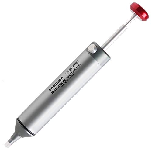
This. Get this. It's cheap, and works like a charm. It's not exactly the highest quality and the fucker takes a few minutes to hear up, but I found it makes it suuuuuper easy to desolder when braids isn't doing the trick.
https://www.amazon.com/dp/B00B88FRME/ref=cm_sw_r_cp_apa_glt_fabc_K3W22B623YMPK0CTHNS1
I highly recommend one of these, in addition to solder braid and some good flux. That desoldering iron/pump has saved several boards when inevitably make mistakes. It's not the most quality tool and it takes like 5min to hear up, but it definitely works.
Maybe I'll get better with solder braid eventually but all I know is this thing works for me every time.
I ran into the same problem with right angle pots. My new method is to solder breadboard jumpers to the lugs and cover the connection in heat shrink. These jumpers are dirt cheap, and are the same ones I use for breadboarding anyway. I don’t like those solid wire jumpers as much.
Basically, get the jumper, put it through the hole in the lug, drown in solder. I never used to do the heat shrink (and it’s not really necessary), but used the bare solder joints as justification to pick up a heat gun.
Edit: fixed my link.
Do yourself a BIG favor and invest in one of these:
https://www.amazon.com/gp/product/B00ABJ4AEC/ref=ppx_yo_dt_b_asin_title_o02_s00?ie=UTF8&psc=1
It will make desoldering components INFINITELY easier. Once you get it, desolder all nine connections on the switch and resolder them. I'd also suggest doing the same to the two wire harness connections on the right and left of the board. They should look similar to the one in the middle.
I would suggest investing in a pair of flush cutters, so you can trim those leads better (unless you just haven't trimmed them yet, the camera angle is a bit tricky to my eyes); these are my go-to:
Get a digital multimeter
Set it to 20 V (DC) and then measure the voltage. You do that by connecting the black (COM) lead to ground and the red (V) lead to a test point in your circuit (e.g., the voltage supply jack, then test points in your circuit. You do this when the power is on of course.
This will tell you if you have wired up the DC jack properly. If you didn't check, then you have a 50/50% chance of getting it right. I tried to look at your photos, can't say for certain if it is correct. Your effect will not work without proper power. ;-)
In debugging, you have to use deduction to rule out various root causes. Don't assume anything is correct. Put on your detective hat, and everyone (everything) is a suspect ;-)
Hope this helps.
I've gotten this and was pretty pleased: https://www.amazon.com/gp/product/B07H5P5846/ref=ppx_yo_dt_b_search_asin_title?ie=UTF8&th=1
I have trouble finding good breadboards. Some people recommend buying expensive name-brand ones, but I don't think that's wise because no matter how well built they are, they're effectively disposable. The grips wear out.
For protoboards or strip boards, just be sure to scrub with a green scotch pad, or steel wool or something before using. You need to remove oxidation.
Commented above with etching info!
The book is here! Death: A Graveside Companion
Partner got it for me for Christmas since we are both artists and reference death a lot in artwork. Also a good source for images and inspiration for crust punk/doom/death/metal artwork.
I use 22 AWG stranded.
https://www.amazon.com/dp/B00NB3SYGK/
I personally wouldn't go bigger than that for pedals. Between the size and being stranded I feel like I can get stuff done without feeling like I have to be overly delicate. Having different colors is, again personally, a must. Some people can wire everything up in one color and not get confused, not me.
I've recently gotten an IR loader pedal (specifically the Joyo Cab Box) and I'm currently using it at the end of my effects loop chain with the through output returning to my amp and the balanced out to my recording interface. However, my amp (the Jet City Custom 22) has the volume controls before the effects loop in the chain - meaning that in order for me to get any output through the IR loader, I have to have significantly audible output through the speakers as well. For live scenarios this is fine, but I'm wanting to be able to record silently at home. I need a load box.
I've been perusing all kinds of schematics online regarding resistive load boxes (I don't need anything reactive for my purposes) and I'm trying to simplify the design as much as possible. What I've come up with so far is this:
The idea is to use two 100-watt 4 ohm resistors (such as these) with a switch to select between 4 or 8 ohms to match various amp output impedance values. This is then in parallel with an adjustable voltage divider (using a potentiometer wired as a rheostat as R1 and a fixed 1k resistor as R2 in the voltage divider) to act as an adjustable line-level output that could then go into an IR loader or any other line-level input you wanted.
Does this design look fine? Am I missing something fundamental here? Is there any reason this wouldn't work - or worse, be dangerous?
I have been using inkjet paper, and it works fine. As stated, I put a couple coats of clearcoat on it after printing and before transferring. The directions on my paper specify acrylic clearcoat, but I used Rust-Oleum clear paint and it works fine, too.
This is the paper I'm currently using: https://www.amazon.com/dp/B077TMFVL9
The main traits of breadboard are size and whether or not they have the right tension for inserting leads/wires.
Too loose and you get bad connections and waste time troubleshooting problems that aren't actually in your circuit... too tight and you bend countless legs trying to shove them in.
I recently got these and was extremely impressed: https://www.amazon.com/gp/product/B077DN2PS1/ref=ppx_yo_dt_b_search_asin_title?ie=UTF8&psc=1
No idea how long they'll last but so far so good.
Basically this one, but mine has a 3500mw laser head: https://www.amazon.com/Engraver-Engraving-Machine-Printer-7-6X7-6CM/dp/B07N2PP3LG/ref=sr_1_2?dchild=1&keywords=laser+engraver&qid=1610600996&sr=8-2
The kits that are more expensive have much better instructions, that being said....Amazon has DIY Kits around $30USD. cheap af pedal
I’ve successfully made the delay and the tremolo. Don’t get the fuzz pedal, the instructions are unclear and illegible. I’ve bitched 2 of them! ***too embarrassed to post here due to my rats nest wiring jobs.
- Just a regular electronics soldering iron. The kind with a pencil looking tip, not u-shaped wire (i.e for heavy duty pipes and such). This is a great option to get started. There are other kits of this exact iron, with various brand names, and different sets of tools and accessories.
- Probably, but I wouldn't worry about it. I've only used PedalPCB and Aion and they both do quality work.
This really depends on the soldering Iron. A really cheap one might have the 'all chrome' coating over a solid copper tip - These are awful and miserable, blacken like you said, and if you take off the chrome coating, the cheap copper tends to pit really bad even if you're super careful - use steel wool, and go gentle to not take off this coating. This is just going to kick your ass over and over again, and it's not really your fault - some irons just suck. The best you can do is make sure to not leave flux on it by wiping on a damp sponge, and also making sure most of the solder doesn't stay on with a brass sponge - Anything that stays is going to react with the coating and either make it blacken again, or worse, pit it, making it completely useless.
On the flip-side, even some of the other cheap irons (I got a $20 digital soldering iron off amazon; the one that's just a pen-style iron with six interchangeable tips - Find it Here if you're curious, thing's actually Amazing) have a properly coated tip, which is a much harder to mess up the surface of. Zero problems with this kit.
You can't go wrong with these:
https://www.amazon.com/GLS-Audio-Profile-Pancake-Speaker/dp/B003UIC78W
I bought that exact item about 6 years ago along with some mogami cable and they've been rock solid.
Have you been using a mechanical pump? I gave up on those and use the braid now. I’m far from an ace at soldering and I’ve managed not to destroy too many parts fixing mistakes (I actually destroy switches more than anything else). I use this braid: MG Chemicals 425-NS #3 https://www.amazon.com/dp/B00424S2C8?ref=ppx_pop_mob_ap_share
If you just mean the jack, then it doesn't have polarity. You decide the polarity when you wire it up by choosing which leg to solder which wire to. Edit: and if you need help figuring out which is which you can use a multimeter or post a link/pic of what you have.
If you're talking about a power supply, then yes you probably want to buy a center-negative supply. A cheap ($7'ish) one will be fine for now. e.g. this.
Click the links to see an example of a jack vs. power supply if that's not clear. And if this doesn't help feel free to follow up because there may be a miscommunication due to terminology.
I have had good results with these:
Alpha Metals #am31605 4oz.032elec... https://www.amazon.com/dp/B000G36BYU?ref=ppx_pop_mob_ap_share
MG Chemicals 425-NS #3 No Clean... https://www.amazon.com/dp/B00424S2C8?ref=ppx_pop_mob_ap_share
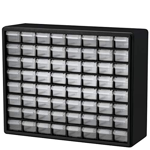
I have two of these for pedal parts and they’re AMAZING. I’ve one for onboard components and one for offboard.
The onboard toolbox top contains my flux and desoldering stuff, etc. The offboard toolbox top has my audio probe, tape, multimeter, etc.
Edit: this amazon price is very much more than I paid, but it’s this style. Look around
Edit: i got them for an equivalent of about £12 each.
Something I've been doing recently, that you may or may not like, is using a $30 rubber stamp kit from Amazon and a $10 pad of Stayzon black ink to apply my pedal controls, names, etc. It gives it a really cool rustic look. I can't even remove the Stayzon with a screwdriver once it's dry, and I generally do not enjoy water slide decal design or application. I'd rather be messing with components and soldering!
You could actually get 2 Mooer Pitch Box for quite a bit cheaper than that - Here they are for $54 each on Amazon.
I have a $40 AOYUE 40ish watt adjustable soldering station (it's a clone of the hakko old 936) I got from Amazon, then added a real hakko 1/16" chisel tip. These have been reviewed by a bunch of people including EEVBlog and Big Clive on YouTube. They are solid and inexpensive. They are Chinese, so if you ebay or aliexpress etc around you'll find identical ones under other brands. There's also now several slight variations, like digital control etc with very similar looks and naming (937 are the digital for example). All the variations have the same soldering iron. They take genuine hakko tips, and since chisel tips are better than thin pointy "pen" type tips for our usage, I went ahead and just got a real tip. Had this for like 3 years and it's never let me down.
Plus you can find them as low as $19+shipping from some places.
https://www.amazon.com/Aoyue-AO936-AOYUE-Soldering-Station/dp/B000VINMRO
I'd get a 1u rack blank and go from there. Amazon has 19" rack blanks for 10$ or so, I'm sure you could get cheaper somewhere else. I think most rack blanks are steel, so you'll have to have a good drill to make your pot and jack holes. How wide is your rack, just out of curiosity? 19" is standard for most compute/audio applications, but it differs, especially once you get into synths, where eurorack is the new standard...but that's usually a standard 19" rack insert that lets you rack many 3u panels vertically. Eurorack is a bit weird, but Amazon sells a bunch of different blanks there too. I haven't messed with Eurorack blanks yet, so I'm not sure what those are made out of, but I suspect aluminum, since that's what most eurorack gear I've seen is made from, and that's easy to mill.
Good luck!
Thanks!
It's a little hard to say because I started ordering parts in larger quantities for multiple builds this time. Taking a quick look at tayda.com (where I get most parts) and Amazon, I get this:
| Part | Cost |
|---|---|
| PCB | $10 |
| Spray Paint | $3.50 (For the green. I also use clear coat over the vinyl, but I use one can for many projects.) |
| Enclosure | $5.50 (though it was part of this pack) |
| 2 knobs | $1 |
| 2 toggles | $1 |
| 2 pots | $1.20 |
| CA3080 IC | $4.95 (pretty expensive, as components go) |
| Resistors, capacitors, transistors, diodes, trim pot, DC jack | Maybe $1 to $2 total. Tayda's prices are great on things like this. But for most of these I bought multiple so I could use them in other projects. |
| Mono jacks | $1.74 |
| Total | $30.89 |
It depends on the component. Resistors and caps usually either work or not, and even really cheap sets tend to be within rated tolerances. I just buy the cheapest sets of those that have the values I want.
Transistors and ICs will depend on what you're getting. Common and still produced values are cheap and easy to get. Again, just buy whatever's cheap and gets you what you need. Watch out for fakes or seconds when buying out-of-production parts like 308s or 3007s. Best to get those from reputable places (smallbear, Mammoth, etc), because they're expensive and it's easy to get burned. I'd really look at the values you're getting when ordering ICs and possibly transistors in bulk. Those parts are usually really specific to a build and buying a lot of values might leave you with a bunch of unused parts.
The Joe Knows sets are good, if a little expensive. They tend to be well sorted, which is nice, but not something I'm willing to pay more for. Like this set of resistors is going to be just as good and is significantly cheaper than the equivalent Joe Knows set. There's certainly nothing wrong with the Joe Knows stuff though - if it has the values you need at the right price, go for it.
You can also score some great bulk deals on ebay and alibaba, but you'll be stuck waiting for overseas shipping a lot of the time. I'd go Amazon for an initial order and then shop around when you refill.
According to all the stuff I've seen, no, Black connected to 9V, grey connected to the resistor.
Also, I just got the brick from amazon. https://www.amazon.com/Reverb-Module-Accutronics-Digi-Log-Horz/dp/B00E1P197S/ref=sr_1_1?ie=UTF8&qid=1515099350&sr=8-1&keywords=btdr
They stopped making them, but you can still find them at several different sources online, Amazon for example.
No need to use adaptors yet.
I have a few that I bought off Amazon. I like these ones the best: https://www.amazon.com/gp/product/B077XK8V4G/ref=oh_aui_detailpage_o01_s00?ie=UTF8&th=1
I don't recommend buying one of those starter kits that's got a bunch of useless pieces of crap included. Spend a little more at the beginning and get the parts that you need.
​
ETA: Here are the parts I recommend...
Hard jumper wires. These make your breadboard tidy and don't get in the way.
Soft jumper wires. These get in the way but they are really handy.
Big assortment of poly caps.
Big assortment of resistors (they are not all equally useful, but you will quickly discover which ones you need to buy in bulk)
Big assortment of electrolytic caps.
Big assortment of ceramic caps (I've actually been using all poly caps, but these are really handy)
Assortment of on-board potentiometers.
Make your own power supply with some soft jumpers and a dc plug. (Cut a male-male jumper in half and connect each half to a lug on the dc jack).
LEDs
Assortment of diodes (but honestly a bunch of 4001, 4148 and 1n34a will get you most of the way there)
Trimpots are nice but not necessary
Assortment of transistors (just having 5088 and 3904 will get you pretty far)
ICs can get a little wild, but you will for sure want some TL072 or equivalent (TL082, JRC4558, etc), and probably some LM386 or equivalent (I like the JRC386).
Ah yeah those will cut but you need something that will cut shorter. I found these on Amazon they work great!
+1 on this. For most pedal making purposes it'll get you a lot farther for a lot cheaper than trying to upgrade your multimeter.
Here's a specific example of what they're referring to: https://www.amazon.com/Aideepen-Mega328-Transistor-Capacitance-Battery/dp/B01M0UXHYY/ref=sr_1_20?dchild=1&keywords=component+tester&qid=1601437190&sr=8-20
I have this one and it's been great for testing caps, identifying transistors, measuring hfe, and more.
Silicone Repair Mat, Magnetic Soldering Mat Heat Insulation Electronics Repair for Cellphone, Laptop, Watch, Drone, Heat Resistant Pad 932°F for Soldering Station Iron 17.7inch x 11.8inch (Blue) https://www.amazon.com/dp/B01N10MA2O/ref=cm_sw_r_cp_api_i_f4lzFbKH918NQ
Well, right now it's plugged in to this, but the 12v rail is only rated for 100mA - I haven't measured it to see if there's any voltage drop, but it seems to be working fine. There's a higher-current version that would be better suited - but I'm planning on building a power supply anyway, so I'll dedicate a regulator to it soon enough.
Oh it is. If you haven’t yet, I’d suggest using sockets for transistors and diodes. You can change the sound fairly drastically in any pedal by playing around with them.
You can cut these to whatever number of pins you’d like.
uxcell A14081900ux0270 Single Row Straight Header Strip Socket, 2.54 Mm Pitch, 20 Piece https://www.amazon.com/dp/B012ACSO4Y/ref=cm_sw_r_cp_api_i_NfEiFb87FXCM7
TUOFENG 24 Gauge wire-Stranded Wire Kit-24 AWG Flexible Silicone Wire(6 different colored 30 Feet spools) 300V Hook up Wire Kit Tinned Copper Wire https://www.amazon.com/dp/B07G2BWBX8/ref=cm_sw_r_cp_api_i_JlAgFb3D3C4ED
I don’t have a drill press either. It’s actually really easy using the automatic punch. You just put the tip on where you want to drill the hole and push down. You’ll hear an audible click & feel it as well. Now you have a perfect indentation to start your smaller drill bit. You could probably go straight to the step bit after using the punch, I just like making a starter hole with a smaller bit prior to using the step bit.
Here’s the step bit I use. It’s cheap and won’t last forever, but you’ll get through at least 10+ pedals with it. Does every hole size you’ll need for a pedal enclosure:
uxcell Step Drill Bit HSS 3mm to 13mm 11 Sizes Titanium Coated Straight Flutes Hex Shank for Metal Wood Plastic https://www.amazon.com/dp/B07T33RCCY/ref=cm_sw_r_cp_api_i_fakgFbTPDKPW0
I started with BYOC last year, I believe their Green Muff was my first. Quickly became obsessed. Read everything I could, and watched as many YouTube videos that I could find (and still do both). Then I found PedalPCB and went nuts.
Drilling is easy, many pcb suppliers also provide a build document complete with a drill template you print out. I start with a small automatic punch, then a small drill bit and finish with a step bit (or uni bit). The 3PDT’s are wired using PedalPCB’s breakout boards, makes it a lot easier and cleaner.
Here’s a link to the automatic punch, a game changer for a reasonable cost:
Neiko 02638A 5" Automatic Center Hole Punch | Adjustable Impact https://www.amazon.com/dp/B008DXYOLC/ref=cm_sw_r_cp_api_i_6ojgFb2AKFXS5
Electronic Projects for Musicians
And if you really want to get your hair wet:
Trick is to use StazOn ink, it’s like a permanent marker. Stuff doesn’t come off.
Contact USA Small 36-Piece American Typewriter Pegz Connectable Lowerase Alphabet Stamp Set, Pool Blue https://www.amazon.com/dp/B01MR03XZ6/ref=cm_sw_r_cp_api_i_LEcgFbX5727PP
I got these from amazon: 24 awg Silicone Electrical Wire Cable 5 Colors (29.5ft Each) 24 Gauge Hookup Wires Electronics kit Stranded Tinned Copper Wire Flexible and Soft for DIY https://www.amazon.com/dp/B07G7R9JQH/ref=cm_sw_r_cp_api_i_2yIxFbVKMQF47
Works well and is very flexible, pertinent, and easy to strip. May not be exactly what you are looking for but might see you through until the other spools are back in stock.
Amazon! I’ll definitely post a demo if it works haha
Build Your Own Fuzz Pedal All kits With 1590B Style Aluminum Metal Stomp Box Case https://www.amazon.com/dp/B06XQL49G8/ref=cm_sw_r_cp_api_i_cktLEbQW2XD0C
the circular ones are from amazon, here . they’re 12 dollars for 10 of them, which is a little expensive, but it’s better than frying a germanium transistor lol
The "better" way to go would technically be a multi-tap transformer or multiple transformers -> 9v regulators which would give you multiple isolated outputs - but it's arguable the difficulty and cost of the build isn't worth the isolation.
The power supply you posted is fine - if you already have a 12v power supply. If not, it's probably cheaper and less hassle to just buy one of these.
Note that power supply isn't isolated despite its Amazon description, but it's about equivalent to your stripboard version. Isolated power supplies need a transformer.
Actually funny I discovered it here. It's another chemical bath that deposits a tin layer atop your copper traces, making them easier to solder and protects the copper from oxidation. I'm on mobile right now I'll edit with a link later but you can get it on Amazon like your etching solution.
EDIT: https://www.amazon.com/MG-Chemicals-421-Liquid-Tin/dp/B008UH3V1K
These things. They're basically heat shrink with a small amount of solder/flux inside.
I've used extractor screws in similar situations and had positive results.
I haven't played with printed cases yet, but it seems like the ability to design the necessary holes and mounting into the case would be a huge advantage for a printed case?
Absolutely a good idea to shield the enclosure: would conductive paint work fine for this? Seems easier to apply to a complicated interior, but I'd be worried about getting it to adhere to plastic.
As long as they’re all analog, shouldn’t be a problem to connect them all to one jack. See this diagram by PedalPCB:
https://i.imgur.com/arIBWYe.jpg
If they’re digital, you’re gonna need something to isolate the power. If you get a big enough enclosure, you could theoretically pop a Joyo ZGP inside and use that to isolate the digital pedals. I use one of these on my board to daisy chain my delay to my tap tempo - without it, I get the clock tick in my signal. I think theoretically it’d work in a situation like this if you embedded into the big enclosure.
You mean these ones ? https://www.amazon.com/Extractor-Absorber-Portable-Filter-Soldering-Fan-Extraction-Prevention/dp/B099ZN8TRJ/ref=sr_1_7?crid=FQXN34XR25FK&keywords=Smoke+absorber&qid=1671382666&sprefix=smoke+absorber%2Caps%2C205&sr=8-7 - They have no HEPA filter and I wouldn‘t trust a carbon filter that‘s so small
I need to start buying bulk components because these shipping costs are killing me. This kit was recommended through the side-bar of this sub but I'm wondering if anyone can attest to the quality? Is there a better option? Usually buy my stuff from Mouser but each pedal averages $20-$60. This kit would cover most components for multiple pedals for only $50. Thanks for any advice!
Do you have only 3 transistors, or you have a variety?
If you have only 3, just use them and you'll get fuzz. Especially if you're using Silicon, I doubt you'll find meaningful differences. You can adjust those bias pots to compensate. But if you want to play around or optimize... Use sockets. You can try rearranging them and you may find slight differences since the gain of each transistor can vary a bit.
If you have a variety, or you want to optimally arrange it, use a component tester to measure the gain of each transistor. Then place them in Q1, Q2, and Q3 depending on how close they are to the recommended range.
That's good to know it wasn't my googling skills, I wasn't able to find anything with those digits. This MM, saw a YT review that said it was the best rated one aside from FLUKE. But yet again, it is Amazon lol. It lines up on the left side of the connections, EBC with the nudge at the bottom right.