
What are
/r/breadboard's
favorite Products & Services?
From 3.5 billion Reddit comments
The most popular Products mentioned in /r/breadboard:


The most popular Services mentioned in /r/breadboard:
Autodesk Tinkercad
Hackster
Coursera
Circuit JS
Snipboard
Aliexpress
DealExtreme
The most popular reviews in /r/breadboard:
It's a safety thing... if you're never going to be using this in a freezing environment, and it's just for prototyping, it's probably.. "OK," but not not really recommended. You're going to want to use a buck/boost converter if you're trying to achieve anything beyond the 3.3-4.2V range. If you over-discharge the cell, then you have to worry about charge safety as well. If the BMS/protection circuit on the cell (built in) DOES cut the battery off on low voltage (typically in the 3.0-3.5V range), then it'll just shut off and keep the battery safe.
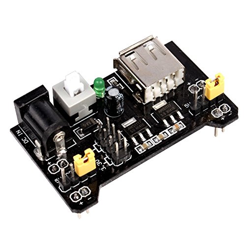
https://www.amazon.com/JBtek-Breadboard-Supply-Arduino-Solderless/dp/B010UJFVTU This is probably a simpler option for just messing around with a breadboard. Depends what you're trying to achieve.
"An arduino" is a little too vague, some of them can run on 3.3V, others are 5V. There are voltage regulators on board that can buck (step-down) to 3.3V, but others won't run.
https://www.youtube.com/watch?v=IT19dg73nKU&t
This is a great video to learn more about breadboard/microcontroller projects.
Belker 12W Multi Voltage 3V 4.5V 5V 6V 7.5V 9V 12V Universal AC DC Power Adapter for Household Electronics - Max Amp 1000mA [BE] https://www.amazon.com/dp/B00ZWU5L0C/ref=cm_sw_r_cp_api_glt_i_HTHC1XRMKVCT9YQVB8B1?_encoding=UTF8&psc=1
Approx $100 USD
If interested, there is also a project tutorial, including code files and instructions:
Did you try using capacitors tied to ground on each side of the voltage step to prevent large jumps in voltage?
Something like this: https://snipboard.io/xXtcfL.jpg
Could you explain what you mean by this clearly isn't DC? As far as I can tell, it is DC as you can see in this working model.
Sounds like a cool project.
If you know the resistance of the bath (you might be able to measure it with the meter), you could make up a voltage divider like you mentioned. You need to make sure the resistors you use are large enough (in wattage) to dissipate the extra energy without getting too hot.
A relatively inexpensive adjustable power supply like this ($40) would be easier and safer. https://smile.amazon.com/Battery-Eliminator-Supply-Outputs-Regulated/dp/B01M3372KU
For even better control, a lab power supply (search for adjustable DC power supply) would be able to limit voltage and current; it will provide X volts at up to Y amps (you adjust both limits). If the resistance drops below X/Y ohms, the power supply lowers the voltage to make sure no more than Y amps flows. Sounds like this would be just the thing for plating (although I don't know a lot about electrochemistry.) Even if the resistance changes, you can limit the current through the bath.
Here's a decent-looking one for about $67. https://smile.amazon.com/Yescom-Precision-Variable-Digital-Adjustable/dp/B00SWK6M0M
It should just turn on. You don't have the ON/OFF pin connected to the input voltage do you? That would turn it off.
Why use an isolated regulator instead of just adding in something like a 60W AC-DC 12v power supply for less than $15?
https://www.amazon.com/GALYGG-110V-220V-Universal-Regulated-Transformer/dp/B06XRBYN4Z/
Do you have a wiring diagram?
You're on track then! :) If you don't need the voltage divider to pull 3.3V separate from the Pi, I would avoid it. If you want to solder the in-between board, don't let me stop you! Practice is practice! What I would probably do is just us something like the 5 pole one of these: https://www.amazon.com/AUSPA-Lever-Nut-Assortment-Connectors-Pack-30pcs-x/dp/B06XP8J311
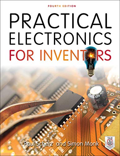
This is the best book on the subject and really got me far in creating original circuits: My copy is as dog-eared and bookmarked as could be.
Nicolas Collins Handmade Electronic Music: The Art of Hardware Hacking
https://www.amazon.com/dp/0415998735/ref=cm_sw_r_cp_awdb_t1_57MCAbAZ0WC52
More than hacking and mods, really gets into playing with ICs and such.
Have fun.
I concur with this. If you are talking portable and not a 110AC deal, put a 12v car or motorcycle battery at your launch station with power routed to each launch pad. You can go with a microcontroller if you want but I think it would be overkill and I would prefer physical switches in any event. Big buttons to mash. You can get some 18-5 or 18-7 thermostat wire:
https://www.amazon.com/Southwire-64169622-Conductor-Thermostat-Power-Limited/dp/B0069F4HHC
(here is some 14-5 if you're really worried about the gauge)
https://www.wireandcableyourway.com/14-5-soow-portable-cord-600v-ul-csa.html
If using a 5 conductor as an example, you ought to be able to take power to the buttons on one wire of the five through a master kill switch, then use fire buttons on the other four that return the individual launch pads to ground. One cable from launch control to launch station.
Hmm. It looks as if the power supply module is something like this. https://www.amazon.com/JBtek-Breadboard-Supply-Arduino-Solderless/dp/B010UJFVTU/ref=sr_1_fkmr2_1?ie=UTF8&qid=1475424871
If so, it seems to take a 6-12VDC input, probably the same barrel size and spec that would fit an Arduino Uno's power jack.
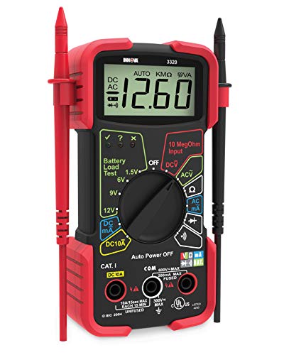
Without a multimeter, you're kind of blind. If you can afford it, I'd pick up a cheap one at least until you can finish your kit or find a better one. I actually bought an HP 34401A off eBay a few years back. Not cheap (around $500US), but well worth it for the precision and functionality.
Just starting out, pretty much any multimeter will do, although a digital one will be easier to use. Something like this looks reasonable for most hobby use: https://www.amazon.com/Etekcity-MSR-R500-Digital-Multimeter-Continuity/dp/B00KHP6EIK/ref=sr_1_1?ie=UTF8&qid=1475425053&sr=8-1&keywords=multimeter
With the multimeter, you can test the output of power supplies and your power module, to make sure the voltage is within spec. Later on, you'll want an oscilloscope -- but they're not too terribly expensive, either, these days.
If you can't test the resistance, make sure you "stack" the resistors in series (end to end) rather than in parallel (side by side). Sorry if this is obvious to you; I'd rather mention it and get an eye roll than not mention it and have you burn something out by providing it with a much-too-low resistance.
Feel free to reply or PM if you have questions. I teach electronics as my day job, and enjoy helping others get started.
That stuff is pretty good, but I especially like the silver-bearing solder, like this. https://www.amazon.com/Cardas-Soldering-Eutectic-Silver-Solder/dp/B015X68HXW/ref=sr_1_2?ie=UTF8&qid=1469639712&sr=8-2&keywords=silver+bearing+solder
I'd go for leaded solder with no silver rather than a silver-bearing lead-free mix, though. Lead-free solder is harder to use, especially with no flux/rosin. No wonder you were having problems.
If all you want is a backlight, some LED's hooked into a DC power brick would probably do the job. There are loads of handy calculators out there that will do the math for you too, like this one. It might also be easier to use an LED strip like this.
As for light spread, I would probably use some frosted glass or something of that nature. Not sure on that though.
You can also try asking in /r/diyelectronics; we're a pretty new community happy to talk about exactly this sort of thing.
Is this a decent multimeter? http://www.sparkfun.com/commerce/product_info.php?products_id=9141
I've also noticed that there hasn't been an update in 16 days, but you did respond to my comment pretty quickly last night.
I know you specified earlier that these lessons will be posted when you get time, but do you have a time frame of when this course will be finished (and possibly how in-depth you'll go into it)? I'm really looking forward to get down and dirty with my new materials.