
What are
/r/rfelectronics'
favorite Products & Services?
From 3.5 billion Reddit comments
The most popular Products mentioned in /r/rfelectronics:


The most popular Services mentioned in /r/rfelectronics:
QUCS
HackADay
SemanticScholar
Circuit JS
Brilliant.org
CircuitLab
Micro-Cap
COMSOL Multiphysics
Ngspice
Veusz
Instructables
Inkscape
Imgur
DealExtreme
FileTransfer.io
The most popular reviews in /r/rfelectronics:
Those are good intros sources BTW.
Honestly the biggest issues:
Building things - NOTHING in engineering is meaningful without building things and verifying their operation empirically. This is especially true in RF/µW.
Testing things (without the right test equipment building things can be hit-or-miss - which is how RF/µW gives the illusions of being "black art"). This means having access to certain equipment like VNAs and SAs plus a lot of the connector and calibration paraphernalia (which is $$$). Find a lab at school that has these if possible. Or a local company. I really solidified my RF/µW knowledge working for HP T&M (divorced/remarried as Agilent, soon to be divorced/remarried as Keysight). I'd done ham radio and even worked with radar systems for the Navy but I had gaps.
Getting familiar with "distributed model" as this trumps lumped model elements in RF/µW circuits. Get familiar about things like return loss, source mismatch and noise figure which come up all the time as "fundamentals" akin to KVL/KCL or mesh analysis in lumped model circuits.
SPICE's closest approximation to distributed modeling are transmission line devices which don't actually do things like s-parameter types of transmission/reflection; you have to go to sim tools like Agilent's ADS or other harmonic balance simulators like Qucs to really have meaningful simulation capability. SPICE is fundamentally a lumped model simulator only.
Learn the system level architectures and circuit level design patterns. Low frequency lumped circuits have these but there are a whole other set for RF/µW. Many are "radio" models (this is where ARRL pubs are useful even for digital SDR). But there are also other oddments you should know such as circulators, directional couplers, waveguide types and modes, etc.
Assuming that you are here because you are interested in RF and electronics, I would recommend “Experimental Methods in RF Design” a book published by the ARRL which teaches major building blocks but focuses on providing practical circuits you can build.
Inductance Calculations by Grover is THE classic text for calculating inductance.
https://www.amazon.com/dp/0486474402/ref=cm_sw_em_r_mt_dp_EZ503NTV5VPA188097XH
However, that's for calculating inductance values. You may be more satisfied with a good E&M text or better yet, Feynman's lectures on physics.
Inkscape is quite good once you have built up a library of parts. It lacks decent snap arrows, so I recommend roughing your diagram out on paper first, and you certainly couldn't use it as a mind mapping tool. The Align/Distribute tools are top notch though, and really save time.
One other hint is to turn off "scale line width" in preferences>behaviour, then you can easily resize things without the lines becoming inconsistent.
Wikipedia has a lot of components in .SVG format you can use with Inkscape, but the quality varies.
On another note, you could just use a schematic drawing package, but have "fake" components for filters etc. That way you get the correct behaviour of lines, and already have a wide library of built in symbols, you just need to add some more generic ones.
qucs is another option for free filter design software. It has a filter calculator buried in the tools menu capable of calculating Butterworth/Chebyshev high/low/band pass filters.
For very simple system level stuff like gain, noise figure, and worst-case cascaded IIP3 you can do all of that with excel, or a pencil and paper. Microwaves101 has some useful pre-made spreadsheets for cascade analysis in their downloads section.
If you want to actually simulate things QUCS can do a fair amount, and it's free. It's not the same style of tool as AWR system simulator or Simulink in Matlab, but might be sufficient for your tasks. I don't have much personal experience with it.
I don't think frequency really affects the accuracy of any of these tools. What affects the accuracy is having high-frequency models of the building block circuits and the interconnecting transmission lines, and QUCs built-in models for T-lines should be pretty good.
Also keep in mind the Python toolset. Personally I use PythonXY distribution with Scikit-RF library. Very handy, and totally free. You can read in and analyze touchstone files and cascade two-port networks in here.
You may want an in-line attenuator
If the source is outputting 100mW = 20dBm, and the receiver expects -93 dBm (defined as "S9" signal strength), you need about 110dB of attenuation or a couple of these: https://www.amazon.com/Coaxial-Attenuator-6-0GHz-50ohm-60dB/dp/B07JMRSQV1/
Steer and Lee maybe if you want more RF Circuit perspectives. Innumerable if you are looking to branch out.
Michael Steer's Book - AWR E-Learning free download Others at that link too, great way to learn AWR if you are in academia.
So its looking like your s-parameter matrix is assuming 50 ohm ports for all of its s-parameters right? Just do a parameter conversion to whatever other matrix you want (Z, Y, A, etc.) This might help, but its too late for me to be crunching the numbers myself:
For lower frequencies (AM), you may be able to get away with using opamps instead of transistors. For example.
This may be a good way to start out, as the part counts are smaller and opamps require less tuning and tweaking than transistors.
See also, Figure 116 in the best appnote ever written.
I would imagine Qucs has the capability. I haven't used it in a while, but I know you can load LTSpice files on it and it has some similar capabilities (to some extend) to ADS.
Yes, exactly the concept! You can easily play "what if" games with this free tool http://tools.rfdude.com/RFdude_Smith_Chart_Program/RFdude_smith_chart_program.html .....Tell it the center frequency, and starting impedance. Turn on "Q arcs" and play with component values and network topology. You can make the match "Q" anything you like, but beware of component losses, more parts make more loss..... anyway the tool is free and easy to use for just such matching emergencies..... sorry it runs in Windows, I don't know if it works in WINE.... edit... also, after you figure out the topology you like, you can do real simulations in QUCS, it's free too.... http://qucs.sourceforge.net/ Agilent will have kittens when they figure out a free tool is about as good as ADS for most easy simulations.
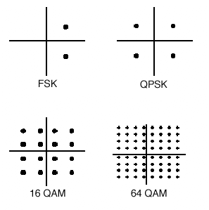
Here is a visual of PSK and APSK:
Here is a visual of QAM:
The company I work for uses ADS and HFSS. Both of these packages are too expensive for "casual" use, or teaching yourself about RF circuit simulation. QUCS does a fine job replacing ADS in most situations, and it's free. I don't know any free replacement for HFSS http://qucs.sourceforge.net/
Presence detectors that I have read about usually use RFID tags (passive and active). You could use triangulation or an RSSI measurement to detect proximity or spatial location. Then a heatmap could be made, for example a wi-fi heat map can be made by walking your laptop around.
More advanced would be systems that try to detect people behind concrete walls. MIT's Lincoln Labs "x-ray" system uses the S-Band (2-4 GHz) to see through walls.
What exactly are you trying to do?
EDIT: With ultrasound you typically have very narrow beams, so you need to sweep through the room with an array of transducers with beamforming or the like. You'd also have to do some processing on the return signals. A simple idea might be to create a baseline "image" of a room (echo and reverberation profile, aka room impulse response) and when it changes you'd know something in the room has changed.
The mathematical theory on this is usually covered in a graduate level math class. The go to textbook on this subject is
Probability, Random Variables and Stochastic Processes https://www.amazon.com/dp/0071226613/ref=cm_sw_r_cp_api_glc_fabc_1Vd4FbCJCH098
Source: Flunked this class in graduate school.
I bought one of these to mess with: https://www.amazon.com/dp/B00SK8LNYG
Currently $9.84 (free S&H) for a breakout board. 100kHz to almost 300MHz, controllable over I2C. Two independent clocks (choose frequency, turn off and on, and possibly relative delay (never tried delays) plus one dependent one. Works great on the Arduino, possibly a little finicky on the ESP32 (might be me). The chip itself is something like $1-2.
You might be interested in software defined radio, or SDR. The dongles have become ludicrously cheap, and there's tons of open source software available. They can perform some basic spectrum analysis, too.
Stimson's Introduction to Airborne Radar book is a great place to start. You can find it free in pdf form if you google it (unless you really want to pay almost $300...)
​
It's more of a primer on radar in general, not specifically phased arrays and SAR -- but it does have chapters on those topics.
​
As far as hands-on, check out Greg Charvat's coffee can radar which can be built for a few hundred dollars. There are also FMCW modules on ebay/amazon that might fit the bill.
Common TV splitter/combiners are usually transformer-based, and DC passing is not uncommon (for example this one; there are many many functionally equivalent ones on Amazon that may be cheaper). However, your 3MHz requirement on the low end is tricky. Is that parameter negotiable? Most of these cheap splitters are good down to 5MHz.
Also, are you looking for a 75 ohm or 50 ohm part?
I guess Microwave/RF Applicators and Probes for Material Heating, Sensing, and Plasma Generation, 2nd ed. would be interested for you. At Amazon that costs a lot but 3lib can help ))
Ham here. If you want a cheap and easy one then use the AD8317 that you can buy as an easy to use module on Amazon etc.
Just put an antenna on, hook up power, and read the output voltage on your multimeter. I use an op amp to invert the voltage output since in this case the higher the signal the lower the voltage output.
The AD8313 module is lower frequency buy higher sensitivity and dynamic range. Perfect for 2M/70cm work.
they make some very affordable spectrum analyzers nowadays. things like this:
​
you will need one of these if you want to design and build/test your own RF circuits. Otherwise, you will simply be staring at the circuit and wondering "Is it working? what is wrong with it?"
I feel like you will need to know power amplifier design fairly quickly. The consensus is to read Cripps's book. You should have a basic understanding of RF concepts like S-parameters, P1dB, impedance matching, Smith chart, etc. This stuff is covered in Pozar's book.
But the gist of PA design is to design impedance matching networks to transistors to present an optimal impedance to the transistor. By doing so you can get desired Pout, PAE, gain, etc. You also gotta figure out how to do this while keeping the amplifier stable, not to overheat, etc.
Razavi has a new book. Have only read the first few chapters, but it is good so far.
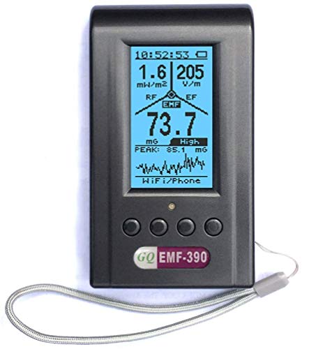
Well it's very real if you have any questions regarding this i can help you , i need a hand held rf / emf meter Like https://www.amazon.com/Advanced-GQ-Multi-Field-Electromagnetic-Radiation/dp/B07JGJ897T But with full spectrum monitoring not just 2-4 specific bands .i have a SDR but it's no use for me right now
Thank you so much I'm looking for something like this https://www.amazon.com/Advanced-GQ-Multi-Field-Electromagnetic-Radiation/dp/B07JGJ897T But for the whole spectrum not just wifi and 5g bands Do you know any diy build that i can follow
Radio Frequency Systems Architecture and Design.
I find the writing clear and accessible. I also had Plett and Rogers in my masters degree, so I'm a bit biased.
Can you solder? Something like this works very well for reading total RF levels up to 10 GHz (both wifi bands) with a multimeter and if you hook it up to a speaker/amplifier you can hear all the digital bleeps and bloops.
https://www.amazon.com/dp/B08VGJQ6HZ?psc=1&ref=ppx_yo2ov_dt_b_product_details
sweet.
i used to be able to get protoboards pre etched with 0.1x0.1 pad on one side, 50 mil thick FR4, and a solid ground plane on the backside. i made all sorts of such circuits on it, up to around 2.6 GHz operation. The company i used to get them from stopped making them. but to give you and idea, thew were kind of like this one (except this one has 50x50 mil pads)
​
since there is a solid ground plane on the back, you can get a very low inductance path for any grounding or bypass caps. herever you needed a ground, i would just drill thru the board with an 0.031" drill bit, and thread some tiny tin plated bus wire thru the hole. also you could sting together many chip components without the need for wire interconnecting most of them, do to the large pads. you could crowd up to three chip terminations onto one pad.
in the future, i would more recommend you use something like that. the solid ground on the back really works better for RF, microwave, and highspeed digital signals.
​
you will need an adapter and cable to attach it to the spectrum analyzer.
You should start with existing receiver board like flysky
Or something to control motors.
https://www.amazon.com/Quickbuying-Scisky-Brushed-Control-Compatible/dp/B072Q9CH44
In fact your should define if it is Rx only, what it controls, servos, ESC, motors, do you want to Tx camera data
What weight and battery/voltage.
I doubt you want to start with programming a micro, laying out a pcb, doing filter design, keeping power and frequency writing FCC rules, adding in battery mgmt, finding a controller that is compatible
https://www.newark.com/keysight-technologies/e4982a-030/lcr-meter-426-x-277-x-222mm-13kg/dp/40Y7232
​
that at least covers your frequency range.
i would carefully read the spec sheet to see how to hook your inductor coil up to it without ruining the measurement. maybe call an app engineer at keysight?
Free: Look up stuff old stuff an old HP guy named Doug Rytting. Then google Keysight application notes on de-embedding. It’s all about signal flow graphs at the end of the day.
$: You could also buy this book. https://www.amazon.com/Handbook-Microwave-Component-Measurements-Techniques/dp/1119477131/?_encoding=UTF8&pd_rd_w=xd7zl&content-id=amzn1.sym.38bb2fca-b288-4f86-afed-5132328a7c6d&pf_rd_p=38bb2fca-b288-4f86-afed-5132328a7c6d&pf_rd_r=...
PS: IMS just happened last week. I literally saw grown men act as fan girls over this author. They wanted to get their book signed and have their photos taken with him. 🤷
/u/HW_Enthusiast /u/Lord_Mel_Gib
Thank you. I seemed to have found a device that does what I need.
Cuddeback 1385 Home Wireless Image Receiver for G or J-Series Cuddelink Trail Cameras https://www.amazon.com/dp/B07DKGMHZS/ref=cm_sw_r_apan_i_PGTPQKX5YNQDEEPHXQS1
Surprised nobody’s told you to go read Balanis, so I’ll be that guy.
Go read Balanis.
It has all the math you’ll need to see that antennas are not only a precise science indeed, but also a massively MASSIVELY deep topic.
Everyone else here has good advice too, so definitely follow that too. But also do yourself a favor and get Balanis from ZLib.
Thanks! And fun fact: below is the entirety of the URL that’s actually necessary. The rest is for Amazon to track who’s clicked the link and from where
https://www.amazon.com/RF-Explorer-Handheld-Spectrum-Analyzer/dp/B00H4B9A0E/
A setup like this is called passive repeater.
I haven't done that myself so I'm not sure how well it would work.
As for the second antenna touching the phone, it would have to be designed with that in mind. There are phone holders with such passive couplers built in, but again I haven't tested that myself so I don't know how well they work. Also they might not be designed for all modern LTE bands.
>reflections at 80w into a non matched impedance will fry your FE. > >Only one way to find out though :)
I've had good luck debugging 2M antennae with this SWR tester:
MFJ-259D MFJ259D Original MFJ Enterprises Antenna Analyzer, VHF/220 MHz (100-160 KHz, 280-520 KHz, .53-230 MHz) - Replaces MFJ-259C https://www.amazon.com/dp/B082Q4G3SM/ref=cm_sw_r_apan_i_JGKYXETD83GXGW3ACH06?_encoding=UTF8&psc=1
It should give you an idea if you're going to cook your TX without cooking your TX.
I've found experimenting with antennas without some way to measure them to be frustrating AF. Being able to measure some basics gets me into the first rung of the ladder.
I wouldn't want to try to using an old pipe as an antenna without several hundred dollars worth of measurement equipment. Being cheap is expensive!
Your balun looks a lot like the one I ordered.
Balun One Nine v1 - Tiny Low-Cost 1:9 HF Antenna Balun and Unun with Antenna Input Protection for Ham It Up, RTL-SDR, HackRF and Other HF-Capable Radios. Great for DIY Dipole and Longwire Antennas https://www.amazon.com/dp/B00R09WHT6/ref=cm_sw_r_apan_i_DFAJNSR25JJ2FZDXYV5K?_encoding=UTF8&psc=1
Mine's a 1:9 balun though. Looks like I'll need to make my own 1:1 balun with a ferrite bead and learn how to solder with these brass sma conectors. Obviously I'll need equal windings on both sides of a ferrite bead to get 1:1, but is less total windings better or more windings better with these small transformers? I learn a lot by trying and failing so I might just have to experiment myself.
TL;DR: (personally) I'd upgrade RX antennae and not fudge with TX
For my money, I'd be upgrading the receiver antennae with a pair of patch antennae if it's going to be stationary, rather than messing with the transmitter -- I'd be worried about creating a worse impedance mismatch on the TX that would forever hurt efficiency (i.e. range).
Whether the receiver antennae are for diversity gain or whether they're for multiple-in multiple-out, they should be the same/similar types, not mix-n-match. At my last workplace we had a similar problem with computers in the far corners not having a good WiFi connection (slow or dropped connections). I ordered three (discontinued?) antennae from Amazon with a staggering 16dBi of gain and the difference was night & day.
I don't know if anybody can find that exact one? I looked but it seems to be off the market now :/ hope that helps, anyway <3
This is not something where you just find an equation, plug in a few numbers, and you are done. Based on your requirements you'd select an architecture, and specific information on your requirements will allow you to set requirements for the components that make up the transmitter in the architecture. You might need to evaluate multiple architectures because there are often many ways to design a given system. And all of this is traded off against other requirements such as cost, size, weight, and component availability and lead time.
Your requirements are not well enough established to create a design. "Reliable output" is a vague description with no specific meaning.
For example you'll want to know the following:
- What is the signal input format (e.g. digital, baseband I/Q, IF), bandwidth, and modulation type?
- How accurate does the frequency need to be, with what phase noise, and stability? This is a function of several factors such as regulatory requirements, the receiver, and your signal type (high order modulations require lower phase noise).
- Are there EVM and adjacent channel or out of band emission requirements?
This is a good book which should help you: https://www.amazon.com/Microelectronics-Communications-Engineering-Technologies-Rappaport/dp/0137134738
Unpopular opinion, but first-hand experience is a great way to learn :D . If you're not sure whether something will work, set up an experiment and see if it does -- if it fails, the troubleshooting experience will be valuable, and if it works the first time, then it's time to treat yourself :)
But also, there's a book called High Power Audio Amplifier Construction which helped me a lot -- it's not specific to RF design but there is still mention of it AND a lot of the concepts from the audio spectrum and from amplifier design, still apply to RF design :)
In particular, it goes into detail about how the different sub-sections of an audio amplifier interact with each other, and I think it'll be a good mindset in general; i.e. seeing how different sub-circuits (even the premade ones) can interact with each other.
Hope that helps :)
- First, understand a basic thevenin source delivering power to a load resistor. You can do the derivation yourself to see that max power is delivered (assuming no power supply limitations) when the load resistor is equal to the source resistance.
- Power delivery requires voltage and current to be in phase. For the same voltage and current the less they are in phase the less power you will deliver. For a load with a non-real impedance you will need to cancel out that reactance in order to deliver the most amount of power.
Conceptually that's really all there is to matching for optimal power delivery. That said, optimal power delivery isn't usually the goal, and for a real RF power amplifier matching in this way won't actually get you the most power because you have a current limited source, so instead of conjugate matching you need to do a load line match. Matching often has many conflicting design goals, such as stability, gain flatness, etc.
My recommendation is to start with Gonzalez and work your way up from there. By far the best exposition of microwave circuit matching that I've ever come across.
https://www.amazon.com/Microwave-Transistor-Amplifiers-Analysis-Design/dp/0132543354
It's safe. You plug your charger in to this light socket adapter that breaks out the plug
Just an example of what you need
I would think you could use a yagi type antenna.
I wasn’t able to find that MS156 connect on any other cable except that one on AliExpress. This is the other option but it seems really only for testing: https://www.amazon.com/dp/B01AQXMMME/
Here's the valenta paper: https://www.semanticscholar.org/paper/Harvesting-Wireless-Power%3A-Survey-of-Conversion-in-Valenta-Durgin/013b4a0084843f2779434e558e5f9d4c9ab0c271
And here's Alanson Sample's dissertation: http://www.alansonsample.com/publications/docs/2011%20-%20Alanson%20Sample%20-%20Cutting%20the%20Last%20Cord%20with%20Wireless%20Power.pdf
For what its worth, RFID systems have been using wireless power transfer for a decade. It's a wonderful tool for powering smaller devices or lots of small devices, but I wouldn't expect to run a car from it. There is a lot of work in beamforming and targeting energy to a specific area that can massively boost efficiency (no matter the nay-sayers in this thread).
NASA has been for years looking at using a satellite to harvest solar energy and beam it down to the earth as a microwave. I just put in a recent paper about something similar, so we'll see how these things continue to develop. I wouldn't worry about the Fresnel zones and all that, unless hitting peak efficiency is your goal. In that case, just couple some coils and do near field transfer.
Uhhhh... This wouldn't happen to be the "Comcast Business" Cisco DPC3939B, would it?
Replace it with a Motorola/Arris Surfboard SB6183.
Not of the details, but we had some fun jacking around with it once we were finished taking measurements. It's still in the lab somewhere.
Here's a few pictures of us screwing around with it afterwards.
Raab - RF and Microwave Power Amplifier and Transmitter Technologies
Also Cripps' book that someone else suggested, and Grebennikov's Switchmode PA text.
fooling around one day I placed my phone inside normal anti-static bags (like these) with the ends folded over and looked at the number of wifi and cellular bars I was getting (you can still sort of see through the bags). It took 4 layers of bags before both signal indicators dropped to zero and i couldn't call the phone or see it on the network. If wifi and cellular go away, GPS and BT are gone too.
I don't think this is the right place for this question.
This gadget more or less does what you need:
Just disconnect the buzzer and rewire a LED into the circuit.
I don't know why Spectrum / Micro-cap doesn't get mentioned more:
http://www.spectrum-soft.com/index.shtm
I've used all the others and this is by far the easiest, most intuitive package out there.
ARRL handbook
50$ but its THE comprehensive radio engineering reference
hang around the /r/amateuradio and /r/RTLSDR reddits and checkout circuit simulators especially the https://www.circuitlab.com/
Yes, I have made a VNA too.
When I was still student I used AWR with student license to design some of the RF stuff for radar and VNA projects. I don't have a student license anymore, but I still use AWR a lot at work and I really like it.
Qucs is a good open source schematic level RF design software. I have used it in some of my own projects. Haven't really found any good open source EM simulators though.
qucs is a circuit simulator which (barely) can do various simulations of transmission lines and microstrips.
What you are suggesting is to go hardcore and do circuit simulation/calculation by hand. That's actually my ultimate goal but I cannot say that I'm proficient with it yet. Thanks for a code, I will look at it.
Well you should be able to calculate 50Ohm sparams with LTSpice (based on voltages/currents) and then renormalize them to your ((30-j25), (50+j0)) impedances, see e.g. http://qucs.sourceforge.net/tech/node98.html#SECTION001611000000000000000 (might involve some calculations by hand/external to LTSpice)
just BTW: Another Paper I can always recommend regarding matching network synthesis is Dawson, Dale E., "Closed-Form Solutions for the Design of Optimum Matching Networks," in Microwave Theory and Techniques, IEEE Transactions on , vol.57, no.1, pp.121-129, Jan. 2009 doi: 10.1109/TMTT.2008.2009041
See this to understand what I mean. (if you have java) you're looking at 75ohm cables attached to various loads. If the impedance is mismatched, part of it is absorbed and the other part goes back up the cable and gets absorbed by the antenna.
This is mostly a transmission issue, but also applies to reception (especially if you want accurate data). Using a cap, you can tune the antenna to become 50ohms on your desired frequency, which allows all the received power to be absorbed into the 50 ohm meter.
It's for a competition, the official requirements are:
1)Dual orthogonal linear polarization reception, using two separate sub-units with relative orientation of 90 degrees.
2) Efficient radiative coupling over the band from 50 MHz to 500 MHz, with return loss of more than 8 dB over at least 80-320 MHz (i.e. S11 < -8 dB).
3) Total projected span of the structure (Width*Breadth) to be within 1 square meter, and an extended conducting reflector below, defining the "ground plane" (for the entire array), is to be an integral part of the design.
I've already done a bit of modeling, a double-sided Sierpinski fractal antenna (both plated and wired) at 300MHz. However, the result isn't very good, S11 is horrible and I can't isolate the issue at higher frequencies. The simulation for a fractal of depth 1 are available https://filetransfer.io/data-package/ZayJUpWI , though I'm just not very satisfied with the overall idea. Something is off and I can't quite put my finger on it. Though that might be because this is my first time designing an antenna.
Buy an EMF meter.
https://www.amazon.com/Advanced-GQ-Multi-Field-Electromagnetic-Radiation/dp/B07JGJ897T
I have one.
It is in the RX and TX of this RC car https://www.amazon.co.uk/gp/product/B07XH2WY95/ref=ppx_yo_dt_b_asin_title_o00_s00?ie=UTF8&psc=1
You could make a half wave dipole antenna, they are a good match for 75Ω coax. It will need a balun though. Since it's for receiving, I would make a folded dipole which is about 300Ω and use a 300:75Ω balun.
If your asked specifically to use the Taguchi method then the modal analysis method won't be of much use since it's not an optimization method.
Characteristics mode method uses characteristics mode of an antenna to determine resonant frequency and/or the length and width of a patch. With patch antennas the TM10 is the dominant mode since it has the lowest resonant frequency. There are other higher order modes.
For my design the addition of the slot added a new resonant frequency near the 5GHz band and tuning slot length, width and position I was able to get the farfield radiation pattern that I wanted.
I found this Electromagnetics and Antenna Optimization using Taguchi's Method. it's edited by Constantine Balanis who is a legend when it comes to antenna design. This might help you.
You can use an ad8307 with an audio amplifier to do this.
Conceptually, system noise is affected most by the noise figure of the 1st amplifier in the receive, as well as its gain. That's why LNAs are used, due to low NF (noise figure). Also, dB is waaaaay easier to do the math in.
This is off the top of my head, not a book source so take it with a grain of salt:
Each cascading amplifier in series uses the gain of the PREVIOUS amplifier, and divides its own NF by that value. So if you have amplifiers: LNA, A1, A2, A3 with associated NF NFlna, NF1, NF2, NF3, and gains Glna, G1, G2, G3 the equation for system NF is something like:
NFlna + NF1/Glna + NF2/G1 + NF3/G2 [dB]
Note, noise temperature is not included here, this is purely the recieve chain.
I would look up in the book "Satellite communications " 2nd edition by Pratt, Bostian, and Allmut, but I am not near my copy. Maybe you can find a PDF, but they explain it there quite well.
This is the transducer: https://www.amazon.com/Ultrasonic-Thickness-Fingertip-Transducer-Collection%EF%BC%88PT-04/dp/B01MRTVJMY/ref=sr_1_1?keywords=pt-04+probe&qid=1553659468&s=gateway&sr=8-1
​
I can't find a datasheet anywhere online. I also emailed the customer service of the company that makes it and they couldn't provide me with one. They just provided me with the specs listed on the amazon listing.
Thanks for answer. IF are between 10^13 to 10^15 hertz but here you can find a IF tx/rx that work on 38KHz....
Great, thank you for the detailed answers! Will calibrate the VNA and add footprints for the matching network by the antenna feed point. I assume that I can't rely on the chip manufacturer's documentation, since it's inconsistent and it assumes that the antenna is on the PCB in the air (whereas I will be encasing it).
So, to calibrate it I'm getting one of these to play with https://smile.amazon.com/gp/product/B07BXTL2NL
The matching inducuctor should be determined based on matching the gain and noise figure optimally, but an analysis of gain, stability and noise circles. For reference you should look at the Gonzales book
https://www.amazon.com/MICROWAVE-TRANSISTOR-AMPLIFIERS-GREENLIGHT-Guillermo/dp/B00IFXF7CU
​
I would suspect very little difference in 0.9 nH, but you should always put it on your board and check with a VNA to verify the optimal matching. What the vendor tells you may only work on their board and you may need to tweak it a little.
Thank you! That's a good clue.
I know essentially nothing about software-defined radio. Would you say this is a good choice for this project? https://www.amazon.com/RTL-SDR-Blog-RTL2832U-Software-Defined/dp/B011HVUEME/
Nooelec NESDR Mini 2+ 0.5PPM TCXO RTL-SDR & ADS-B USB Receiver Set w/Antenna, Suction Mount, Female SMA Adapter & Remote Control, RTL2832U & R820T2 Tuner. Low-Cost Software Defined Radio. https://www.amazon.com/dp/B00VZ1AWQA/ref=cm_sw_r_cp_api_i_jEO5DbBDS3036. Little $30 receiver you can use with fldigi etc. not sure if it has signal strength.
What if I get one of these 315mhz transmitters and swap the 315mhz crystal for the 295mhz crystal: 315mhz rf module (amazon). It looks almost identical to the 433mhz transmitters that are popular and is only a few mhz off from my target 295mhz.
I have not seen others that are as affordable as the NanoVNA... there is a “miniVNA” on amazon that goes up to 3GHz but its $500
https://www.amazon.com/dp/B07JNLDJBJ/ref=cm_sw_r_cp_api_i_GIkLDbCND1GR9
Some good books where mentioned above but they are very technical. If you want to dive in and build a radio I would start with this: Experimental Methods in Rf Design (Radio Amateur's Library) https://www.amazon.com/dp/0872598799/ref=cm_sw_r_cp_api_i_HACGCbKDCA7QA
I have not, too expensive.
You can smooth out pla quite easily with a mini file set like <strong>this</strong> one.
I use waveguides equivalent T-circuit. I derive it form the A matrix of the waveguide with connected transformers. Result is close to the one, given in the Waveguide Handbook. The only difference is Z0 n^2 instead of Z0. So no mixing of A, Z and S matrices together, only transformations between them.
EMC for Product Designers by Tim Williams
Highly recommended
Lots of second-hand older editions on AbeBooks
You can probably find references like this (not cheap):
https://www.amazon.com/Nonlinear-Microwave-RF-Circuits-2nd/dp/1580534848
In general most RF/microwave is presumed linear. And when it's not it's device-level transistor/diode models exactly like you'd have at low frequencies. E.g. s-parameters and other 2-port parameters are 100% linear only.
Most of an undergrad EE is about "How to keep it linear" where "it" is literally everything.
You do run into nonlinear concerned but often they are handled by things like Class C amplifiers (which are merely filtered to eliminate the introduced nonlinear effects), or "load-pull" testing which look at mismatch effects caused by nonlinearity in the gain cell.
RF Microelectronics by Razavi is very, very good. It was recommended in my RF IC seminar and I found it very helpful.
I got a lot of mileage out of Electricity and Magnetism for Mathematicians, by Thomas Garrity: http://www.amazon.com/Electricity-Magnetism-Mathematicians-Equations-Yang-Mills/dp/1107435161
He does a good job with the intuitions behind the theory; this might help you understand how everything relates to what you want to do. It will also help plug the holes that are sometimes left by engineering instruction in the math. In the US, at least, engineers are less formal about the math and don't always clearly explain what motivates professional conventions.
This is a newer edition of the book I learnt RF stuff from back in the day: http://www.amazon.com/Modern-Electronic-Communication-9th-Edition/dp/0132251132
Not sure if it's going to be relevant enough for you without knowing precisely what you want to know, but might be worth a look to see.
I recently picked up a copy of Modern Small Antennas by Fujimoto and Morishita. Very useful resource for small antennas.
To do an electrically small antenna design you typically need a 3D field simulator. They are not cheap.
Does anyone have any experience with the text "The Electronics of Radio" by David Rutledge?
A friend recommended it to me.
I think you may need to be a bit more specific. There are thousands of textbooks that talk about propagation and/or modulation.
I was recently reading this: http://www.amazon.ca/Wireless-Communications-Andreas-F-Molisch/dp/0470741864
But I would imagine it is much to advanced for you. And I guess that begs another question. How much detail do you want on propagation and modulation formats? Do you want to know about them in the context of the RF circuits or just their properties in general?
Well, pretty sure. I watch all the commands on the SPI bus between the processor and the TI CC1101 RF transceiver inside the C7089R Wireless Outdoor Sensor, http://www.amazon.com/Honeywell-C7089R1013-Wireless-Outdoor-Sensor/dp/B004MH7YE2 . I see them doing all sorts of configuration stuff, and enabling the transmitter, and writing to the transmit FIFO, but I never see them enabling the receiver or reading from the receive FIFO.
It's a real puzzle.