
What are
/r/arduino's
favorite Products & Services?
From 3.5 billion Reddit comments
The most popular Products mentioned in /r/arduino:
![Official Arduino Starter Kit [K000007] (English Projects Book)](https://m.media-amazon.com/images/I/41BlK004WQL._SL500_.jpg)


The most popular Services mentioned in /r/arduino:
Hackster
HackADay
Aliexpress
Instructables
Autodesk Tinkercad
Processing
Circuit JS
PlatformIO
Banggood
MakeUseOf
Fritzing
eBay
Google Sites
Thingiverse
Alibaba.com
The most popular Android Apps mentioned in /r/arduino:

Bluetooth Electronics

ArduinoDroid - Arduino IDE

Arduino Bluetooth RC Car

MSMBle

MIFARE Classic Tool - MCT

Spaceteam

Sky Map

NFC TagWriter by NXP

Medisafe Pill Reminder

ElectroDroid

Cool Tool - system stats
ESP8266 RGB Light
Simple Alarm Clock Free No Ads

DigiHUD Speedometer

Hacker's Keyboard
The most popular reviews in /r/arduino:
I think that is a JST connector. Let me verify.
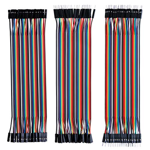
You could just cut and solder extensions on your existing cable.
Taking all the sarcasm out of the other posts: wires are the correct answer. A pack of these https://www.amazon.com/Elegoo-EL-CP-004-Multicolored-Breadboard-arduino/dp/B01EV70C78/ref=sr_1_2_sspa?crid=1DZVVNPD0HK7A&dchild=1&keywords=jumper+wires+male+to+female&qid=1625274166&sprefix=jumper+wires+male+to+fe%2Caps%2C157&sr=8-2-spons&psc=1&spLa=ZW5jcnlwdGVkUXVhbGlmaWVyPUExOE1ISTg2WVVCRjJQJmVuY3J5cHRlZElkPUEwOTAxNzYzM0FUQTA2MU5UWkNIRCZlbmNyeXB0ZWRBZElkPUEwOTQ1MzIxMUVLUFZPSjk1OTFYOSZ3aWRnZXROYW1lPXNwX2F0ZiZhY3Rpb249Y2xpY2tSZWRpcmVjdCZkb05vdExvZ0NsaWNrPXRydWU= are great to have in your kit.
Firstly, they're not arduinos :) What you have there is a nice little grab bag of embedded systems that will blow an Arduino out of the water, power-wise, but is somewhat less user friendly. The red things on the left are Beagle Boards - the top one is an xM, not sure about the bottom one (edit: that's a c2, of course). They are, simplistically, a lot like a Raspberry Pi without the community support. They're a full system-on-chip, they'll run a version of Linux, they have USB, video, networking, etc. Excellent platform for learning ARM programming and embedded development. Steep learning curve, though.
The one underneath is another ARM board, but with an inboard gyro suite. This is closer to the Arduino, it's not a mini-pc in the way the beagle is, but again, more powerful, less user friendly due to lack of community. The sensor suite makes it more like an arduimu or Razor/freeimu board.
So what you have there is a powerful robotics or embedded platform. The Beagle board is a full system, the STM is a full sensor suite and real time micro controller, both with a chunk of power. I'll hunt up some docs to get you started, it would be handy if you know C, but there are some tutorials out there.
Welcome to the world of ARM. The question is, what do you want to do?
Edit: try this - http://beagleboard.org/beagleboard
This has been around for a while... you can even re-flash your arduino over Wi-Fi.
Heck, you can just run Arduino code directly on the ESP...
The simplest and cheapest solution would be smth like this. https://www.amazon.de/70Stk-Doppelseitig-Lochrasterplatte-Kit-Lochrasterplatine/dp/B07BDKG68Q/ref=mp_s_a_1_1_sspa?keywords=lochrasterplatine&qid=1667510758&qu=eyJxc2MiOiI1LjYwIiwicXNhIjoiNC45NiIsInFzcCI6IjQuODAifQ%3D%3D&sr=8-1-spons&am...
Neat. Did you guys take inspiration from the Adafruit LED Matrix Hourglass or one of the kits. Or did you do it all from scratch?
Make a diffuser screen for the front to hide the wiring and make the LED's easier on the eyes. If you place the screen a little distance from the LED's, it will blur the image a little making your "sand" particles form together into more of a mound. Will probably enhance the effect.
A suggestion. When doing work with AC use just one hand. I learned this from a mentor when I was a kid. He had me sit on one hand for most operations (when possible).
The logic is that the higher amperage stuff can't travel through both hands and pass through the heart. What ends up happening is it just reminds you to be much more mindful of what you're doing. I don't always do it now, I do a lot of house wiring, but I think that training made me much more aware of what I'm doing.
EDIT: Relevant hack a day post
TL:DR there was an internal breakup after claims of a betrayal, both sides formed groups claiming to be The Real Arduino, and one side was forced to trade as Genuino in Europe for a while because of a trademark issue. As a result the two sides spent a year or two trying to sue each other and badger suppliers into only using their products instead of making things the community wanted. Meanwhile the ESP8266 became hugely popular while the Arduinos were too busy bickering to do much about it
There's a longer writeup of it here, but eventually they came back together and said they've worked things out.
Now get yourself an i2c screen and realize how much easier things could have been.
> For the last six months we’ve been working closely with Microsoft to bring the forthcoming Windows 10 to Raspberry Pi 2. Microsoft will have much more to share over the coming months. The Raspberry Pi 2-compatible version of Windows 10 will be available free of charge to makers.
> We’re excited to announce that we are expanding our Windows Developer Program for IoT by delivering a version of Windows 10 that supports Raspberry Pi 2. This release of Windows 10 will be free for the Maker community through the Windows Developer Program for IoT.
Yup! these guys:
https://www.amazon.com/gp/product/B01DC0IMRW/ref=ppx_yo_dt_b_search_asin_title?ie=UTF8&psc=1
You can daisy chain them together, so you get an array of 320 fully addressable (HSV) LEDs to work with in code. The code essentially picks a random LED, sets it to full brightness within a range of a certain hue, and slowly fades it out. The overall hue shifts through the spectrum over time
That's where you're wrong kiddo
Get one of these bad boys and you can pick up a lot of different things. For that satellite tracker you'll need to scale it up for it to be useful tho and add some other rf components (Rf amplifier, lnb, etc.)
VS Code isn't the same as Visual Studio. It's a completely new product from a different team, and it's free and open source. It's the most popular IDE now according to stack overflow. RIP Atom and Sublime text, I guess.
don't know what you mean there. its not 1990 anymore, linux needs drivers for nothing - scanners, printers, cameras, arduino, uart's, webcams.... i'm always amazed when trying to help a friend who runs windows at just how much crap you need to go through just to get a printer or trackpad to work lol.
apart from which we're talking about usbserial which supports cp2102, pl2303, ftdi, ch340 etc. out of the box.
Nothing http://arduino.cc/en/Main/ArduinoBoardZero . Arduino.org is the site from the italian factory that manufactures the official arduino boards. They don't actually hold any copyright to the name hence: http://hackaday.com/2015/02/25/arduino-v-arduino/
$50, for a soldering iron? That's ridiculous.
You can get a whole kit for like $20. And it will work just fine for years.
https://www.amazon.com/hothuimin-Electronics-Adjustable-Temperature-Desoldering/dp/B079MH7VX1
Now someday you might want to get one of those fancy adjustable kind, especially if you are doing tricky stuff like surface mounted components. But countless high school and college kids learned on a basic hot poker.
I had that issue with a DS1307 connected to an ESP32, I switched it out for a DS3231 and with its temperature compensation precision, I haven't noticed any drift over the last couple of weeks.
The ds1307 I was using, like yours picked up a minute even after 1 day of use.
If you want to make sure you're getting proper boards, buy them from a proper electronics distributor like Mouser or Newark. You're less likely to be hit with fake products that way.
The place I'm working at uses a mix of genuine and "arduino compatible" boards. Cheap ones for testing or in house stuff where it may be likely to be broken. Then official ones when it goes out to customer.
That said, the Uno logo is wrong. It's probably a counterfeit board.
I was just googling "electronic price tags", they could change the price via RFID. I wonder if there is a standard protocol for it.
Check out the comments in this page, it's not the same one as yours but it might give you some ideas.
http://hackaday.com/2011/04/07/hacking-electronic-price-tags/comment-page-2/
And, no I don't know of a safe way to open it other than "just be really careful" lol.
Edit: Once you figure out how to change the price you could "go shopping" at kohls https://www.youtube.com/watch?v=nCDuQyVknoc
Visual Studio is probably the best IDE out there in my opinion, and Visual Micro provides a plugin for Arduino. Code-completion, debugging, great serial input/output...it's all I use anymore.
The community edition of Visual Studio (basically the full and complete version) is free now since Microsoft has shifted their strategy so it no longer requires any big expenditure.
I'm 56 retired and still enjoy working with Arduino. I just recently purchased a Prusa 3d printer and am really enjoying learning it along with fusion 360. That said it really requires having a goal in mind, as it is more difficult to just sit down and learn to make an LED blink. There is a Make book called making things talk that starts out basic but gives lots of ideas on ways to use Arduino in useful ways. Making Things Talk: Using Sensors, Networks, and Arduino to See,... https://www.amazon.com/dp/1680452150/ref=cm_sw_r_sms_awdb_t1_TngvDbVTQ4STT
Hope that helps!
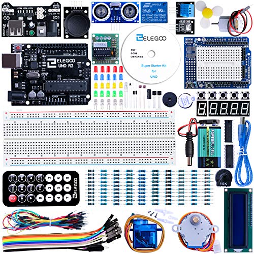
A starter kit that comes with the motion sensor and that little dot matrix display, costs $60 USD from amazon (includes the arduino, a lot of other sensors, and some wire as well):
If you just want an arduino, the motion sensor, and the dot matrix display it can all be had for a lot less, about $20-$25 from Amazon. Or if you are willing to wait, about $7 from aliexpress. I would recommend a starter kit though.
There are a ton of these in Amazon's database. For example, for $110 someone will remove the CPU from your computer and replace it with an ATTINY85...
I.. uhm.. I think you need to think in code, feel the code, express yourself with the code. Programming isn't about doing some homeworks, it's more about communicating your thoughts to the computer and other programmers. I know your focus is those lame homeworks right now, but never let school get in the way of your learning!
Often, your programming thoughts themselves will be ill-formed. Like, you thought something, go to program and find out your thoughts about a process were wrong. It might happen that you won't know for sure that something is possible (and that it will work like you expected) until you program it.
It's likely that you won't ever fully understand your own programs either, because most programs are too complex to be understood all at once. That's what bugs are made of, misunderstandings on how your program works. Programming by then is mostly managing the complexity of increasingly large programs. (dividing programs in "functions" is one such tool - it is an ability required by this exercise, even though it may seem pointless in that contrived example)
I will lay some points
You need to learn C. Seriously. Arduino code is technically C++, but C would mostly work and you won't be using fancy C++ things anyway. Also, professional code would be done mostly in C. So, learn C.
The best book to learn C is K&R. It's very small and very clearly written.
I don't have an Arduino resource, because my professor wanted us to target the Atmega microcontrollers and not the high-level Arduino libraries. I read this avr guide and the datasheets (that guide has basically all the important tables from the datasheet, but is easier to understand). You probably should look for Arduino tutorials and documentation.
From a response in the HackerNews thread:
>"In short, there are two companies calling themselves “Arduino” at the moment. One, Arduino LLC was founded by [Massimo Banzi], [David Cuartielles], [David Mellis], [Tom Igoe] and [Gianluca Martino] in 2009, runs the website arduino.cc, and has been directing and releasing the code that makes it all work. Most of these folks had been working together on what would become the Arduino project since as early as 2005.
>The other “Arduino” used to be called Smart Projects and was the manufacturing arm of the project founded and run by [Gianluca Martino]. Smart Projects changed their name to Arduino SRL in November 2014. (A “Società a responsabilità limitata” is one form of Italian limited-liability company.) They have been a major producer of Arduino boards from the very beginning and recently registered the domain arduino.org."
>Read more at HAD (http://hackaday.com/2015/03/12/arduino-v-arduino-part-ii/)
Also:
> When Arduino got popular, the original team of five spun off a manufacturing company, Smart Projects, to handle the manufacturing and distribution tedium, with 4 of the 5 partners staying in the Development arm. When push came to shove and the development side wanted to make the manufacturing non-exclusive, Smart Projects beat them to the legal punch and registered the trademark before the development team did, forked and uprevved what they could, and cut off the income from sales going back to the dev team.
This seems bigger than just some random dude forking and fucking around.
Some emphasis added.
I used three 12V peristaltic pumps (https://www.amazon.com/gp/product/B07TPMLF5K/ref=ppx_yo_dt_b_asin_title_o02_s01?ie=UTF8&psc=1) although the price was a little lower when I purchased them. They work by using a roller wheel attached to a DC motor to essentially squeeze liquid through the tube. They work pretty well but have trouble with carbonated liquid and can take a little longer when pumping more viscous liquids.
>I used three 12V peristaltic pumps (https://www.amazon.com/gp/product/B07TPMLF5K/ref=ppx_yo_dt_b_asin_title_o02_s01?ie=UTF8&psc=1) although the price was a little lower when I purchased them. They work by using a roller wheel attached to a DC motor to essentially squeeze liquid through the tube. They work pretty well but have trouble with carbonated liquid and can take a little longer when pumping more viscous liquids.
But can you plug it into your car? Cause I have a hard time pouring drinks while I'm driving!
If all you are doing is turning it on during the daytime, why not just use a cheap photo sensor? A microcontroller and that RTC seem like an overkill... Especially given the photo sensor will automagically compensate for the time of year...
Edit: who the fuck is downvoting this? It is a valid question! It seems to me you could replace all the digital stuff on here with a cheap photo sensor. It is pragmatic and way more fool proof. I’m curious if I’m missing something.
1: Paul Falstads Circuit Simulator. I taught myself basic and advanced electronics with this tool. Advantage: Runs interactively, i.e. you can modify stuff while simulating. Has ideal models of everything you need. No installation, runs in the browser. You can share circuits by generating a (very long) link.
2: LTspice. Takes a while until you get the hang of it. Advantage: much faster, allows much more advanced maths (both in simulation and in plotting), can use models of real devices.
You post in /r/Arduino - do you want to co-simulate your Arduino code and analog/digital peripherals? I don't know if there is a tool to do that.
http://www.arduino.cc/en/Main/Software Then download source. Then look in arduino-0022/app/src/processing/app/syntax/PdeTextAreaDefaults.java and see
// for 0122, shift-backspace is delete, for 0176, it's now a preference, // to prevent holy warriors from attacking me for it. if (Preferences.getBoolean("editor.keys.shift_backspace_is_delete")) { inputHandler.addKeyBinding("S+BACK_SPACE", InputHandler.DELETE); } else { inputHandler.addKeyBinding("S+BACK_SPACE", InputHandler.BACKSPACE); }
Now look in ~/.arduino/preferences.txt and mirabile dictu we find editor.keys.shift_backspace_is_delete=true
https://stackoverflow.com/questions/8108642/type-of-integer-literals-not-int-by-default
65535 is clearly a positive number and doesn't fit in a signed 16bit int. So its type is 32bit signed.
0xFFFF represents -1 as a 16bit signed number. Its type is 16bit signed. Adding 1 gets you 0.
32767 is the largest 16bit signed number. Its type is 16bit signed. Adding 1 overflows it.
You can use suffixes to change the data type used. (i.e. U and/or L)
Oh no apologies needed! I drew things exactly the same way until I learned about labels.
I too am primarily a Python programmer (it's what I do for a living), and I can mostly get around in C++. The concept of pointers in C++ just doesn't exist at all in Python (or most other high level languages), so that and header files will probably give you the most trouble at first. I think you'll find the rest of it relatively easy to understand.
You'll probably want to move to either KiCad or FreeCad (I think those are the two main free ones), to do your schematic generation to give your poor hand a break.
https://fritzing.org/ (the one I mentioned in my first comment) is really good for beginners, but it's utterly useless for anything other than a complete beginner...if that makes sense at all.
For the coding side of it, I recommend https://platformio.org/ - It's Visual Studio Code with an Arduino "mod" (for lack of a better word). It's what I use, and really love it.
Yup. A brass sponge is good. It helps remove any oxidation that builds up from use of the tip.
Something no one on this thread is talking about is that brand new tip has been "pre-tinned" at the factory. This tinning quickly wears off and is replaced by a build up of oxides.
To properly re-tin your soldering iron tips, you want to first give them a twirl inside a brass sponge, not too much because you aren't trying to sand them down, just trying to knock off any built up gunk. After this step you want to drip the soldering iron tip, while heated up to around 200C, into some acid-flux and each time wipe it off in the brass sponge. After about three times of this hot dip and clean off in acid-flux you should have, cleaned off the entire oxide layer. Now that the tip is clean of gunk and oxides, you want to apply a layer of rosin free solder on the tip until it is coated and looks like the factory new pre-tinned tip. It's important you re-tin with rosin free solder otherwise it will form gunk on the newly cleaned tip as you are wetting it and then letting it cool.
Using an electric solder pot or a container of solder tip tinner is the easiest way to do the re-tinning step after you finish removing any built up oxides/rust with acid-flux.
Link to just the arduino course on its own.
And a note to those unfamiliar to coursera: I realize that it lists prices for the specialization. However, if you just wanted to take courses individually (which is my plan) you can take them each for free; you just won't get a certificate.
Pin 1 to 3 on the PCF8574 are the address inputs anyway. If they are high (open?) you get 0x27 (actually the real address is shifted one bit and 0x4e is for writing and 0x4f for reading), PCF8574A has address 0x3f (actually 0x7e and 0x7f).
https://www.nxp.com/documents/data_sheet/PCF8574.pdf http://hackaday.com/2008/12/27/parts-8bit-io-expander-pcf8574/
It's worth pointing out that actual clones are legit. As in, they're not knock-offs.
Arduino is open source hardware, so anyone can go and make a compatible board and sell it legally, as long as they're not infringing on Arduino's trademarks. Mainly that's the logo and silkscreen design of the board. If you see a Chinese board that looks identical to an Arduino board complete with the logo and silkscreen print, that's a counterfeit. If they use a different design, that's perfectly fine.
Functionally there's only one real difference between the cheapest clones and arduino.cc boards, and that's the USB-to-serial chip that they're using. arduino.cc boards use a smaller ATmega16u2 to handle the USB communication. On Windows the USB-to-serial driver will install automatically. Cheaper clones use a CH340G USB-to-serial chip, and the driver will need to be downloaded and installed manually. After that it works with the IDE like any other arduino.cc board.
However, you can also get slightly more expensive clones that use the same ATmega16u2 chip for USB, and those don't require a manual driver install.
As far as vendors go, pretty much any larger aliexpress seller with decent feedback should be alright, because they all use the same main chips, and putting those plus a few resistors and capacitors on a board is not exactly rocket science. Personally, I've been pretty happy with boards from this seller. Their UNOs with the black header connectors have the CH340G, and ones with blue header connectors have Prolific PL2303 USB chip that should also auto-install the driver.
Have you thought of using a simulator like https://sourceforge.net/projects/arduinosim/? There are a few of them out there besides this one.
Edit: sorry wrong link, that's a project I was keeping my eye on. http://www.virtualbreadboard.com/
Here you go, under $10 on Amazon, don't get hot at 30W, and none have ever failed, so they're bulletproof to me!
https://smile.amazon.com/gp/product/B00J3MHTYG/ref=ppx_yo_dt_b_search_asin_title?ie=UTF8&psc=1
allows using your cellphone as any other input/output : LCD display, Gyroscope, Switches, LEDs, Accelerometer, Magnetometer, GSM, Wi-Fi, GPS etc. see: https://www.kickstarter.com/projects/integreight/1sheeld-replace-your-arduino-shields-with-your-sma
Peristaltic is the way to go. If you want more control, look for one with a stepper motor. That will obviously add a bit more complexity, but will give ultimate control for dosing.
https://www.amazon.com/Peristaltic-Metering-Stepper-Motor-0-88mL/dp/B01LY35CKH as an example.
BTW, the same pump Adafruit is selling is on Amazon for half the price. You are paying Adafruit for the testing and support (which can be a good thing given some of the reviews).
It's an 850 mAh LiPo - definitely a punch for the size. I get them on Amazon: Noiposi 4 pcs 3.7v 850mAh 25c (that's an affiliate link, full disclosure).
Can't get things to paste into reddit nicely, so here's a link to my list: https://sites.google.com/site/kraegar/arduino/getting-started-kit
Take it easy on the rest of my google site, I don't usually post it anywhere, since it's mostly geared for me.
I made a small beginner EPS project with the NodeMCU ESP8266 chip to turn on my PC. The nice thing about this set-up that you don't need skills or third party apps that can have compatibility issues. The major advantage against wakeup on LAN is that you can turn off your PC this way and you can turn on your PC when it is completely shut down.
This is the first time working wit an ESP8266 compatible board and it was surprisingly easy. I made a post on the project in detail if you ae in to the specifics. https://www.hackster.io/Seafox_C/turn-on-your-pc-with-alexa-and-the-esp8266-like-ironman-572b7b
If you have any suggestions please let me know :p
Please tell us more about what you want to do.
Because this sounds like the X-Y problem.
You want to do X, but you think Y is the right solution while Z is a better way.
E.g. if you want to graph data coming from one or more sensors, have a look at https://thingspeak.com/ and the ESP8266 instead of logging it to a sd card, download the data to the pc and then visualize it. Also maybe a EEPROM may be a better solution than an sd card if you only need the data on the arduino, ...
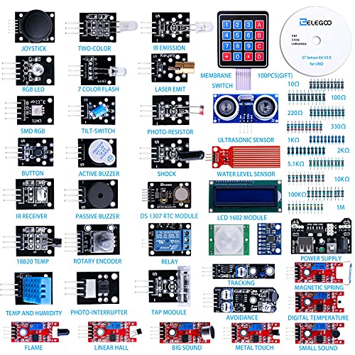
Try an Elegoo starter kit to get a jump on Arduino-related projects to play with. Amazon offers several kits of different components and boards. I like this one for beginners: https://www.amazon.com/ELEGOO-Project-Starter-Tutorial-Arduino/dp/B01D8KOZF4
(sorry about the video quality -- I used YouTube's editor to combine 3 clips and it looks like it chops everything to 1990's tech when you do that...skip to 1:52 to see a closeup...).
I'm almost done building a CNC mill based on Tom McWire's EasyMill (http://www.instructables.com/id/Easy-to-Build-Desk-Top-3-Axis-CNC-Milling-Machine/). I used some enhancements, like teflon tape to reduce friction, from the RepRap McWire Cartesian Bot (http://reprap.org/wiki/McWire_Cartesian_Bot_1_2_(Death_March:_Do_not_build!!!)).
Most of the hardware is from Home Depot; the plexiglas, threaded rod, and teflon tape are from Small Parts, the stepper motors, Big Easy Drivers, limit switches and emergency kill switch are from SparkFun, the 24V 6.5A power supply is from Amazon, and the Dremel power relay a PowerSwitch Tail from AdaFruit.
Right now it's all controlled by an Arduino Duemilanove interpreting commands from the IDE serial monitor and sending them to the AccelStepper library. I haven't decided yet if I'll add a G Code interpreter on the PC or Arduino, add an LCD, buttons, and SD card reader to the Arduino to make it standalone, etc.
As you can see near the end the AccelStepper library doesn't handle interleaving very well so X and Y don't finish diagonal movements at the same time.
I used a 1/16th" bit (0.0625") and the routed slot varies from .085" to .1" so there's still some vibration that needs to be eliminated too....
Most of the circuitry on the aurdino isn't needed for a production run. You can take a bare ATMega and program it with your program, and then it's a fairly simple circuit to get that ATmega running.
Here is an example on a breadboard.
It's actually the backdrop for my text editor (ATOM). To do this I use the "Ghoulish UI theme" by "angela-d" -->https://atom.io/themes/ghoulish-ui .
Then I go into the theme settings and in the background image directory, i put the gif, jpg or png file I want to use for my background.
Hope this helped!
Well yeah. Here's one: https://www.aliexpress.com/item/Allwinner-A31-chip-ARM-Cortex-A7-Dual-Core/2027726555.html
Here's a more powerful one. https://www.aliexpress.com/item/Allwinner-A13-Cortex-A8-1GHz-The-tablet-CPU/1881239253.html
Microprocessors need a bit more on the board than a microcontroller like the Atmega328, so it doesn't really make sense to buy a chip like that unless you have a really specific goal.
edit: or do you mean "single board computer" rather than "microprocessor"? In that case there's things like BananaPi as /u/johnty123 said. But they aren't particularly better value than a Pi.
Personally I don't know why this gets as much coverage as it does when there is stuff like the OLinuXino-LIME.
https://www.olimex.com/Products/OLinuXino/A10/A10-OLinuXino-LIME/open-source-hardware
- Allwinner A10 Cortex-A8 (ARMv7) processor typically running at 1GHz and Mali 400 GPU
- 512 MB RAM
- SATA
- HDMI
- LiPo battery connector and charging circuit.
- 160 GPIO on 4 connectors.
I'm using processing to capture the screen and detect the color of the pixels on the area of the health bar. It then sends signals to the arduino, that controls the LEDs placed behind the screen.
Here are some of those "dumb" rgb leds. They start at the same point in the color scroll and follow the same pattern, so if you sequenced when you have them power you could have their colors wave like OP's in a very uncontrollable way.
Another vote for the Elegoo starter kit. Whatever you do get I strongly recommend an Uno (or Uno clone) for your first, since you have the "I plugged in all of the wires just like the picture so this should work" advantage.
One extra bit you may also want to get is a small screen that uses i2c, like this one. The super starter kit comes with an LCD that works okay, but it takes a ton of wires, you need to fiddle with a pot, and the refresh rate is really poor. Still worth wiring up the LCD in the kit just to see it in action & learn, but you'll probably want something better as soon as you have a project idea.
I didn't do the android part. I'm using this app it allows you to configure the data you are sending to the Bluetooth module and then you program how to read it and what to do in the arduino
I should have showed it in the video, but I did put it in the description:
> On the face of META you will find a power switch, the idea generation button, and the menu button for switching between META's different generation modes.
The other two modes are board game ideas and indie video game ideas.
Demo video in Update #3
I'm ashamed to admit there's a lot here I forgot. So I compiled all images into a handy printable PDF. Thank you so much OP this is tremendous.
>be visible in this close
If you give me an image circled with what you want to focus on I might be able to try it out. The resolution of that image is around 20um, I may be able to go to 10um. Here is a different sensor at 10um. https://unsplash.com/photos/DYPnjQzd37k
I'm not a big reddit user, and mostly just lurk. But here's my thoughts:
1) Stop thinking of Arduino as a computer. Without getting into a deep semantic fight, it's just a microprocessor with some added stuff to make it easy to use as a hobbyist. Not a computer.
2) Yes, you can most likely use any computer with gpio pins to perform most of the things we ask an Arduino to do. This is a classic Arduino 'Hello World' project, but done on a Raspberry Pi for example. But a computer comes with overhead -- power hungry, larger, and with additional components (both hardware and software) that are unnecessary.
3) As for portability and single-use... The Arduino is fractions of the size (not to mention price) of even single-board computers like the Raspberry Pi, Cubie, or Beaglebone. And an old computer is many times larger than those. Yes, they are often used as embedded processors, which would make them single use -- but that's no different than any of the alternatives in that use case.
You say "I'm not really into electronics, but I really love the computer part of the Arduino". My advice for you is not to get an Arduino then. Arduino is specifically built for hobbyists in electronics. Get a single-board computer, or use your old computer, and tinker with that; I think you'll be happier.
And most likely, one day you'll come up with a project and think "hey, a computer is really overkill in this case. Really all I need is a simple processor to do this one thing" and bingo - you now need an Arduino.
Don't forget that you can't do much with the board alone. It would be a good idea to get a starter pack of electronics if you don't already have one. Some useful pieces that are usually used in introductory electronics courses are: resistors of various resistance, capacitors, inductors, LEDs, and transistors as well as a breadboard and some wire. Also you could find some tutorials to give you more of a purpose, for example: http://www.instructables.com/id/Sleek-word-clock/.
If you are really excited and don't want to wait for your stuff to be shipped you can also try out this program: http://www.virtualbreadboard.net/. It crashes a lot and cannot handle all syntax but it is a good starting point. With this program you can test your code without the risk of frying your equipment if you failed to wire it up correctly.
Finally if you have a little extra cash and you are used to C# programming you can consider Netduino, it is only $5 more at most stores and it allows you to program using visual studio instead of the Arduino IDE.
I'm new myself (within the past 2 months). I have little experience with embedded devices, circuits, and C/C++ - so it's taking a bit to get up to speed. The initial device I built I used this tutorial (I didn't use Javascript, instead I rewrote all of the code in C++):
https://www.safaribooksonline.com/blog/2013/07/25/an-arduino-powered-bbq-thermometer/
Another cool (but limited) tool is Circuits IO - definitely helps with quick prototyping and has saved my ass a couple times from frying my Arduino/components:
Read this and nothing else:
http://www.gammon.com.au/switches
Use this code to handle your buttons from here on. Includes debouncing, handle single-click, double-click, long press and extra long press. Example: want to interact with a display? People tend to use a rotary encoder, which need 3 digital pins. With this code you need a single button, for example: single press to iterate between variables, double press to increment and long press to decrements; extra long press to Home.
I have bought components from Aliexpress that were dirt cheap and arrived with Adafruit silkscreening on them. It's possible you have a knockoff. For example;
vs
Hackaday have a reasonable writeup here.
If I remember right, in the original six or so who ran Arduino one of them owned the factory which made the boards. He decided to sell the factory and his shares in Arduino (I think there were rumours of a fall-out between himself and the other foundersm during which the factory owner quietly trademarked the Arduino name by himself in other regions), which were picked up by Musto.
At this point I think Musto claimed that the others tried to freeze him out and refused to show him documents he was entitled to see, etc., so he proclaimed that the factory itself was the real Arduino and tried to go it alone in order to protect his investment.
I think the others essentially claimed that Musto felt that the factory was the only thing which really mattered and tried to just dump the rest of them to run the project himself.
This led to a period of legal bickering and both companies claiming to be the Real Arduino sending letters to resellers asking them not to support the other guy. Meanwhile, the faster, cheaper, wifi-connected ESP8266 wowed the community, as did the superfast Teensy, so a lot of people kind of just shrugged and left the Arduino group to their bickering while moving on to other things. Not that long ago the two companies announced that they'd reconciled and were pulling together into a single entity.
Boost converters work over a wide range of input voltages.
Here's a one that takes 3-32V and converts it to 5-35V. You would set it to 15V and plug in your battery. But don't use 9V batteries, they're about the weakest battery you can get.
> (CH340 instead of FTDI)
And given the continual woes of working with FTDI and their addiction of trashing hardware, using CH340G is a feature.
I think they are saying that you can use a text editor, like atom, to work on C++ files and than upload to the arduino from the command line inside the editor.
I currently use the arduino IDE, but my workflow would be faster if I could use a text editor, with color highlighting, autocomplete, style linters, search commands, ...
Eagle isn't really free. KiCAD is free & opensource, and is really no less clunky than Eagle. KiCAD can output the files that OshPark will take, and last I heard OshPark was working on accepting KiCAD files directly.
As a regular Visual Studio user (full-blown VS, not VS Code), I installed the Arduino IDE for Visual studio on about my 2nd day of mucking around with Arduinos and haven't looked back since. I love it.
Thoroughly recommended to anyone who knows their way around Visual Studio. Works well with VS 2015 and VS 2017.
Check out Visual Micro: http://www.visualmicro.com/
It actually uses the Arduino IDE tools under the hood, and it's not perfect, but it's all the best parts of a "real" IDE which makes it easier to manage projects that are more than a couple of functions.
Good job! I have always been fascinated with home automation stuff
I would like to suggest that you add some more modules before launching the kickstarter campaign.
I have also made a home management system which allows you to control you home through a website and uploaded it on hackster:
Home Management System
I have a question, will this be an educational product, or a real product that I can install at my home?
Yep! There are several ways, but I’d personally use a multiplexer. They’re inexpensive components (I think I got a bag of ten last time at a dime apiece or something like that.Here are some on Amazon.. There are cheaper ones of Banggood).
You send it the signal you want and a bitwise address (eg 101 for pin 5), and it sends that signal. You then cycle through. It takes nanoseconds for it to switch, so the switching time is quite invisible.
Connect one multiplexer to the power conductor of each column and another to the ground conductor of each row. To light a given light, send HIGH to the column you want and LOW to the row you want.
If you have not done this, if you have some plain solvent (water, acetone, whatever) in your test tube/cuvette you can make an auto self-calibration function. Just sweep the servo and define the particular wavelengths as 100% transmittance with your blank, building up a light profile of the blank, and then measure your sample profile. A cheap spectroscope could help one determine specific wavelengths.
There's no reason that even a LDR like this could not be pretty accurate. Your accuracy loss is going to be the light intensity characteristics of the LDR rather than it's particular wavelength response. That's where the photodiode in the sensor might be a little better since a photodiode's current response to intensity can be linear over 7-10 decades of magnitude to within 1% and LDRs can vary. Now one could have a potentially very precise spectrometer.
edit- clarification
Why would you ever need 134 shift registers? They're 8 bit register.
You'd need 12. to get to 96 LEDs. Or you could get 3 of these 32 bit registers and then just use 4 more digital IO to run the extra 4 bits. It'd only take 7 pins in total.
I've previously experienced strange behavior when connecting multiple SPI components. I corrected it by connecting a pullup resistor on each SS bus.
With the symptoms you describe I can't tell if it has anything to do or not but it's worth a shot.
Sure.
- Use autohotkey to detect when the browser tab changes
- Get autohotkey to run this command to send data to the arduino.
I haven't used a Mega yet, only Unos, and they have all been clones. No issues.
Try these, I really like the Robotdyn stuff.
I wrote a free book that will walk you through creating a library for the TLC5940: Demystifying the TLC5940. The src.zip file on that page includes schematics, and code for all the projects in the book, plus a couple of extra projects that show how to multiplex using common cathode RGB LEDs.
Lately I've been working on a 24-bit gamma-corrected 64 RGB LED persistence of vision toy that uses just 4 x TLC5940 chips. I've been posting all of my project updates on my Google+ page.
You need a 0.1 uF decoupling capacitor between to the GND and Vcc pins of the TLC5940.
Also, do you have a 10 uF capacitor between the power rails on your breadboard?
See my book for detailed schematics: Demystifying the TLC5940. I don't use the Arduino, but the book describes using the same ATmega328P chip, just programmed directly in C99.
Edit: Looking at your video it also looks like you are missing one of the required resistors.
If you want them to be on independent periods, why not just use function calls? Your intuition to make an endless look the continually calls a function is correct, just make sure they're functions, not goto's. Goto is not your friend, for a number of compiler reasons.
Your pseudocode ends up like this:
main(){ while(true){ LEDfade(fadeValue) ServoMove(servoValue) UpdateValues() } }
Edit: except for really edge cases, a microcontroller really only ever does one thing at a time. It just does them really quickly, to approximate continuous effects.
I wouldn't say very limited. The datasheet rates the EEPROM for 100,000 write cycles, which means it would last for 27 years even if you changed the time ten times a day. And some people have tested common EEPROMs to work for well over the rated read/write cycle lifetime. I think it'll be fine.
this is a good starting point that writes new firmware to the radio. You can control it with an Arduino, and you can also control an arduino with the radio. Cool if you want to have a remote control with miles of range.
Curiously, I found a "semi" decent one yesterday.
No match for the real thing though.
but
Virtual Breadboard is MUCH better, but now you have to buy the "modules" :(
A MOSFET is the best bet here, because it doesn't draw any measurable current from the line being monitored. So... a MOSFET acting as a low-side switch, switching an LED on or off.
"File/Import" this into Falstad Circuit Sim:
$ 1 5.0E-6 10.20027730826997 50 5.0 50 172 112 208 112 176 0 6 3.1 5.0 0.0 0.0 0.5 Pin voltage 162 400 80 400 128 1 2.1024259 1.0 0.0 0.0 r 400 128 400 192 0 150.0 f 336 208 400 208 0 1.5 w 400 224 400 256 0 r 336 208 336 256 0 1000000.0 w 336 256 400 256 0 w 336 208 112 208 0 x 72 119 179 157 0 24 Pin to be\nmonitored g 400 256 400 272 0 R 400 80 400 48 0 0 40.0 5.0 0.0 0.0 0.5
The "Pin voltage" slider on the right controls the voltage coming out of the pin. Notice that the LED is off when the voltage is below 2V, and is on when the voltage is above 2.5V. In reality there will be some deviation from those voltages, due to the actual MOSFET you use having a slightly different "Vth" value. (Voltage where it begins to allow current to flow.) But even so, < 1V should be fully off and > 3V should be fully on.
You can use just about any MOSFET, but the easiest one to get will be a big honking power MOSFET:
http://www.radioshack.com/product/index.jsp?productId=2062618
This is way more transistor than this simple circuit could ever possibly need, but it will work fine and it's cheap, so why not.
Don't forget the 1 megaohm resistor between the MOSFET's gate and ground. The MOSFET may not turn the LED off correctly if you leave that out.
A typical red or green LED with a 5V power supply will be fine with a 150 ohm resistor, as shown. If you use a different LED (blue or white), you may need to change the resistor.
Schematic, code and instructions: https://www.hackster.io/mircemk/arduino-repulsive-electromagnetic-levitation-17b1fe
Here's a guide to make your own
It uses a Nano and it's a bit more complex than taping a spray can to the end of a saw.
Edit: I didn't make this. I found it. The link above goes to the guy who did make it.
I looked this up and the first result from Amazon is
MG958 Metal Gear (video game) High-torque Digital data Servo
I'm confused as why it says "video game". Is it related to the game or something? Metal gear? Or is it just... metal teethed? I'm so confused
What worked for me was getting the Arduino Uno starter kit and just making my way through all the introductory projects. As you make progress you will get an idea of the types of things you can achieve with it. Then start jotting down ideas of robotic projects you think would be fun to make. Try and sort them by order of complexity and do the easier ones first. Once you've finished up your first individual projects you should have a really good basis to start tackling some real complex stuff.
​
This was my starter kit: https://www.amazon.com/dp/B01D8KOZF4?tag=%E2%80%9Cardkit-20%E2%80%9D&linkCode=ogi&th=1&psc=1
I bought the elegoo super starter kit off Amazon and I've been SUPER happy with it. For less than the price of an official arduino you get a knockoff board and a ton of electronics to play with. Also arduino is open source so it's completely legal to make knock offs.
Elegoo EL-KIT-003 UNO Project Super Starter Kit with Tutorial for Arduino https://www.amazon.com/dp/B01D8KOZF4/ref=cm_sw_r_cp_apa_CvMWAbFQQHAP4
My company makes the LightBlue Bean. It has an ATmega328 with our own Bluetooth Low Energy module.
We make the Bean Loader for Android. You can write code in an Android text editor and send it to your Bean!
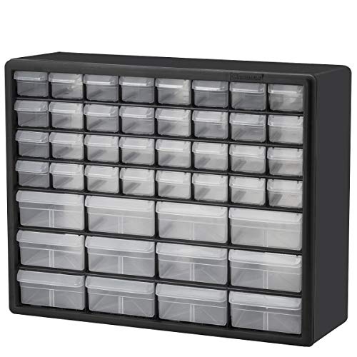
tackle boxes and sticky labels.
Similar to this:
https://www.walmart.com/ip/Flambeau-Tuff-Tainer-Tackle-Box-with-Zerust-5007/16326922
only get 9 or 12 spots per box, but i organize by what it is.
You will need a transistor for each magnet. If I were to design something like this, I would use PCA9685 chips to get additional PWM outputs. You can get these boards for about $2 from China, each one provides 16 output channels and you can use multiple ones at the same time. So that gives you 80 PWM outputs for like $10.
They can drive both MOSFETs and bipolar transistors, but I would try to stick with NPN bipolar transistors to keep the cost low. When it comes to transistors, high voltage/low current is easier and cheaper than low voltage/high current. For instance, a BC337 will do 800 mA at 45V max, and you can buy 100 of them for less than $1.50. If you were to use MOSFETs for something like 5A at 5V, you'd have to budget $0.50-$1.00 a piece.
So you want to wind your electromagnets for a relatively high voltage (maybe around 20V) and a relatively low current. 19V or 20V laptop power supplies are cheap and easy to get, so that would be a good fit.
And if you have 5V circuitry to run at the same time, just add a $1 buck converter to step down the voltage for the 5V components. That way you would still be able to run the entire project with a single power supply.
Been looking at picking up a few.
"Maximum operating speeds up to 2Mbps, GFSK modulation efficiency, Anti-interference ability, Particularly suitable for industrial control applications. 125 Channels, Multi-point communication and frequency hopping to meet the communication needs Built-in hardware CRC error detection, Multipoint communication address control. Low-power 1.9 ~ 3.6V, only 1uA on Power down mode Built-in 2.4Ghz antenna Available software to set the address, only received local Address when output data(Provide interrupt instruction), can be directly connected to a variety of microcontrollers, Software programming is very convenient. Built-in voltage regulator Standard DIP Pitch Interface for embedded applications size: 34mm X 17mm X 1mm"
for $3 each it could be a solution.
http://www.sparkfun.com/products/691 Same chip but from spark fun.
I've seen a couple of projects doing that, but you end up with a more expensive FPGA capturing and processing the video in between the TV and the HDMI source. This would be a good example: http://hackaday.com/2015/04/25/fpga-based-ambilight-clone/
Good advice generally, but I agree with Hack-a-day's PCB design series: friends don't let friends use Fritzing.
The two most common packages people seem to use these days are Eagle and (my preference) KiCad. Once again, I agree with Hack-a-day's conclusion here. Eagle is a very good choice though too, depending on your needs.
If you're going to hot glue an entire arduino board to some glasses, do yourself a favor and dont use an arduino uno.
An arduino can interface with the dispensing hardware, and can sit on a wireless network accepting commands over a REST interface. With an additional RTC module it can be set up with pre-set times. You'll be writing C++ code to control the hardware and run the web interface.
A Raspberry Pi is a single-board computer that runs a full-fledged Linux operating system. It also has GPIO pins that can interface with and directly control your dispensing hardware. You'll probably end up writing the hardware control code in a scripting language (I know there's python bindings, probably ruby and others as well). Then you'll be installing a web server and writing a web app to control it (PHP? I'd use python again).
The RasPi will also be able to handle your webcam. Either with the official camera module, or a USB webcam with confirmed Linux support. It may be the preferable option for an all-in-one solution.
Personally, I'd use an Arduino to directly interface with the dispensing hardware. If you don't already have a 24x7 server that can handle the camera and public-facing web interface, consider using a RasPi to run it.