
What are
/r/esp8266's
favorite Products & Services?
From 3.5 billion Reddit comments
The most popular Products mentioned in /r/esp8266:


The most popular Services mentioned in /r/esp8266:
Hackster
Aliexpress
HackADay
ThingSpeak
PlatformIO
Banggood
Home-Assistant.io
IFTTT
Atom
Visual Micro
mosquitto
Circuit JS
Autodesk Tinkercad
hastebin
PyCharm
The most popular Android Apps mentioned in /r/esp8266:

Wifi Analyzer

HTTP Request Shortcuts
Torque Pro (OBD 2 & Car)

ZeroConf Browser

VLC Mobile Remote - PC & Mac

Blynk - Arduino, ESP8266, RPi

nRF Connect for Mobile

Share GPS

MyMQTT

MQTT Publisher Plugin

Kokonaut Weather Sensors

Tasker
The most popular reviews in /r/esp8266:
The SparkFun board has a trace antenna underneath the "sparkfun" text down at the end. It also has the option to use an external antenna.
The difference you're seeing is that the NodeMCU is basically a carrier board for an AI-Thinker ESP-12 module, which has FCC certifications. The "can" is there to control EMI. The FCC certification allows a manufacturer to basically drop the module into a design without having to go through the process of a separate certification. Just be aware that in order to run a "bare" module you need to add a voltage regulator and a few passives, and in order to program it you need a separate USB-to-TTL adapter. The NodeMCU has all that stuff built-in, which is why it's a convenient way to get started with these things.
The SparkFun has the ESP-8266 MCU, flash chip, and other support circuitry built onto the board and doesn't have FCC certifications since it's a hobbyist board and not intended for use in shipping products. It also needs a USB-to-TTL adapter to program.
https://www.amazon.com/dp/B01NALDSJ0?tag=duckduckgo-d-20&linkCode=osi&th=1&psc=1
These are reasonably efficient.
Go with the D1 Mini from WeMos, not the low-quality clones from other sources.
Sure. I created an api account at https://openweathermap.org/api
Its free, has limitations on how many times you can call. I believe it's one million calls a month for local weather for the free account. I use the ArduinoJson library to parse the information from my account api link.
Why not just use VLC's HTTP interface and either use a web browser, or a VLC remote app?
I'm not an expert so someone please correct me if I'm wrong.
Most people seem to use voltage regulators to get their power source down to 3.3v. The AMS1117 is a popular one, but the HT7333 has a lower quiescent current, which I believe means how much current the regulator will use to provide a stable output voltage. That means the HT7333 is better suited for battery-based setups, but from as /u/gellis12 says, you can do even better with a switching power supply.
These regulators also need capacitors. Their datasheets will typically describe what values to use and how to place them. This is a part I don't know much about, so I'd love if someone else could chime in with more info.
At this point, you need a voltage source. A common one is 5V from a phone charger through Micro USB. Again, someone correct me here. I believe the 5V from the USB pin typically goes through a power diode, and maybe a resettable fuse. Then it goes into your voltage regulator/capacitor setup. 3.3v comes out, and you feed that as input voltage to your ESP chip.
That was a very basic and possibly flawed explanation of how you can power these things, but hopefully it gave you a better idea of what needs to be done.
I have several LED strips (both regular 3-channel and individually addressable WS2812b), a few temperature sensors, and a couple outlet relays to control lights (433MHz from RPi).
At first, like you, I developed my own small webapp to control all of these devices, but it really takes a lot of time and it was far from perfect. I would highly recommend checking out https://home-assistant.io/ . Hundreds of developers have worked on this platform and it works with any sensor / IOT device (with MQTT, you just have to set it up yourself).
My favorite part is the integration with wireless routers to determine if your phone is connected. This way it will know if you are home and you can automate all of the lights to go off when you leave, for example, or certain lights to turn on if you arrive home between certain hours.
Here is my page as an example https://thingspeak.com/channels/289148 (you can use many sensors and customize display widgets). I also use an Android app to display data on my phone and have alerts.
The Pi is the server hosting Home Assistant, gathering temperature readings (via Zwave, GPIO, etc.), presenting the UI, and choosing when to switch the switches. I'm sure you're right that a light-weight web-server could be built right onto the ESP8266 but in my case this is just one component in a full home automation solution based on the Pi.
For your next hat trick, drive those LED’s through a mosfet so you can PWM the brightness.
I’ll even save you days of fustration. The linked MOSFET will be happy with a 3.3v gate voltage and will fully drive your LED’s. You do have to remove the little LED on it though (like one of the comments said)
https://www.amazon.com/dp/B06XHH1TQM/
It is very hard to find mosfet’s happy with a 3.3v gate.
Quick search led me to this: W5100 which even supports PoE and can be connected to an Arduino UNO.
If interested, there is also a project tutorial, including code files, Gerber files, and instructions:
https://www.hackster.io/kutluhan-aktar/iot-heart-rate-bpm-monitor-and-tracker-w-tuya-smart-3f8826
I'll try to share the full source code tomorrow, but I basically used a modified version of my old fixed point arithmetic 3D renderer for avr in conjuction with the TFT_eSPI library that I edited, so it would allow me fast displaying of 1bit bitmaps. The display I used is a generic 320x240 ILI_9341 SPI display from ebay.
I am a big fan of using MQTT for communicating data from and to my esp8266s. It is a protocol that has been developed with low-cpu/memory in mind. It is also the protocol that offerings like Amazon IoT use as backend.
Once the data has been moved from your devices to MQTT, you can connect a wide range of other apps to it to respond to, analyze or consume the data. I use home-assistant.io (which I developed myself) to integrate the data my esp8266s gather into my home automation via MQTT (like this).
I use Visual Studio at my day job and I can't imagine coding without the browsing, code discovery and Intellisense features of VS.
Visual Micro (http://www.visualmicro.com) is great and it is free for hobbyists. I definitely recommend it.
For your 'next up', I strongly recommend against the DHT22, for several reasons. A few years ago you could get a real part from AOSong, but they were erratic and would periodically start returning NaN (Not A Number) results, and had to be power-cycled to correct the issue. Today they're virtually all cheap Chinese clone modules, and they go off the rails more often than not. Additionally, the accuracy is absolutely horrid, even for an authentic AOSong module.
A better choice is the Sensirion SHT30-DIS (usually called SHT30-D on the internet). You can get them for not much more than the cost of DHT22, they're significantly more accurate, and they don't go neurotic on you. I've seen the Sensirion sensors used in several commercial environmental controls, yet never seen a commercial product with AOSong sensors. That should tell you something.
For the internet logging, I've used Thingspeak.com before; it's free, and easy to interface with, one small subroutine to upload to Thingspeak. I like Home Assistant as well, but it's a lot more complicated to work with.
Not much to brag about, but here's an ESP32 out on the garden bench, powered by three AA batteries, reporting over WiFi+https to ThingSpeak.
I'm trying to see how long 3xAA will work, with the ESP32 waking up every 10 minutes to push data to ThinkSpeak.
Oh, also using the RMT to get the data from the DHT11 sensor, which is working really well.
Temp/Humidity stats are public at https://thingspeak.com/channels/357477
Source project is at: https://github.com/hamsternz/thingspeak-esp32-dht11
I have a similar setup running off 2 alkaline D cells from aldi. I think they come in at 12500mAh. A dht22 though, this feeds thingspeak, sparkfun and cloudmqtt. A second unit indoors has a BMP180 and an oled display, subscribes to the mqtt feed and adds indoor temp and pressure to the same thingspeak channel. Outdoor battery unit woke every 5 minutes and was awake for about 6 seconds. I started it on june 21 and it lasted till Sep 12 it seems. So about 100 days. I estimated 3 to 6 months initially.
We manufactured these for a project and decided to make them available on Amazon since we couldn't find them anywhere. Check them out: 19mm Latching 19mm Momentary
I use these: https://smile.amazon.com/gp/product/B07V811RPY/
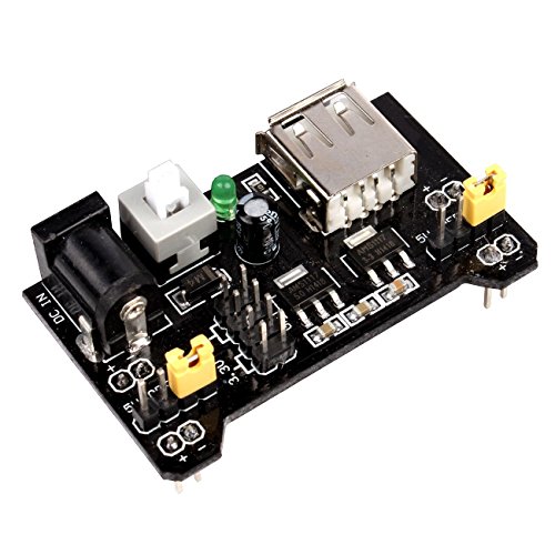
But, to echo Mr DriveBy, if you're using an ESP8266 dev board with a USB connector, I use a little USB power modules with micro usb cable. No wiring, no soldering, and no exposed high voltage
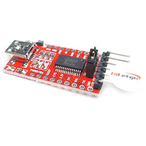
I bought a 5 pack of these off amazon last year for $12.99
https://www.amazon.com/gp/product/B07B92JYDR
"WINGONEER® 5Pcs CP2104 Serial Converter USB 2.0 To TTL UART 6PIN Module compatible better than CP2102"
​
They've worked great, except for the one I ran over with my desk chair. That one doesn't work now.
These are out of stock on Amazon right now, but if you can wait Banggood has them for about $2 incl. shipping.
- not affiliated with Banggood, I just buy a lot of stuff from there.
Just a heads-up, this is the WeMos official store which contains that board here.
I myself prefer the D1 mini V2. They work great!
edit: Actually, the one you linked it's a fake clone. The ESP is clearly seen on the real WeMos version, and if you take a look on the underside of the board, the markings are totally different (but it could be an old version but i doubt it)
to run off battery power, lose the ams1117 .. they draw 5mA by themself. (quiescent current on the datasheet) if you really need a regulator there then find one optimised for battery use. using dual dry cells or alkalines though, need no regulator.
the core voltage on chip is internally regulated to 1.8v and the higher voltage used to drive the RF section. so long as the battery is above 2.2v or so it will work though range will drop. what will also happen though long before that voltage is the impedance of the battery will increase and it cannot supply the current, to cope with this I have a 0.5F supercap across the supply to help with voltage slump during peak load. I also have a 100u or 220u soldered directly onto the esp12 (forget which). esp12 I used as I was using the A/D and used a port pin to enable the voltage divider for reading vcc, the onboard regulator was bypassed.
I have a dual D cell alkaline battery setup posting to thingspeak, sparkfun and cloudmqtt every 5 minutes, once connected it takes not long to post to multiple servers. I am using the readvdd33() function or whatever it is called to post the battery voltage as well, these seemed wrong at first, was saying 4.0v when it was 3.2 but now it seems to have sorted itself out, however the humidity reading on my dht22 seems to have stopped working reliably at 2.8v or so (data says 3v minimum) so i may try a charge pump to boost the voltage there for a sample.
my thingspeak channel is https://thingspeak.com/channels/36227
I have a second unit indoors with an oled display, this subscribes to the mqttcloud server and when it gets a new outdoor temp and humidity reading it takes an indoor and barometric pressure reading and uploads that to my same thingspeak channel. sparkfun data cannot take a partial channel update. you need. every field filled.
It's great that you found a design that fits your needs.
For next time, I can recomm ent AutoCad's (free) TinkerCad for basic designs. You can literally learn how to use it in less than an hour, and it's good enough for most simple designs.
Why not just do push notifications?
Best part is there is no delay as with SMS. Plus ability to ring through alarm channel on your mobile, meaning, will sound even if on vibrate.
Grafana is pretty, and I'm a visual person. It really depends on what your use-case is. In one install, I have six 55" screens set up, all showing different grafana dashboards. You can immediately see status for a lot of data.
If you're using Google Sheets, you can post directly from an esp to google without IFTTT. I might have to write this up sometime.
This is exactly the right solution. It works like this:
- Google docs provides a feature, where you can publish a Google spreadsheet as a web app.
- This gives you a special URL, with an embedded secret token: https://script.google.com/macros/s/SCRIPT_ID/
- Each time you call this URL with a get request, Google adds the parameters for this request as a new line to the spreadsheet: https://script.google.com/macros/s/SCRIPT_ID/exec?time=1464325345&power=1234
- Everyone guessing the token can add her own lines to the sheet. So keep the token secret or add some kind of signature as a separate column.
Thanks 😊
Here is some more detailed description: https://www.hackster.io/leohill/wunderpixel-91b031
I am planing to maka a tutorial for some parts of the project!
You've basically described my motivation behind designing my own sensor (wife didn't like the look of raw perfboards with wires/DHT22 hanging off), so I came up with this. I added an OLED screen for local display and designed a PCB/enclosure to hold it all together. All links to the code/3d files and build videos are posted there. If you have access to a 3d printer, the enclosure is really simple to print, and PCBWay sells the boards for $5 for 5 boards...
Re-posting link from the office as I was editing the post on a tablet on a train and the text got saved half-done with a typo and I couldn't edit it, only delete...
https://www.hackster.io/ROBINTHOMAS/programming-esp8266-esp-01-with-arduino-011389
Check RST connection too.
My goal was to make a cheaper IOT button than the flic. The parts add up to about $10 per button, but others have said you can get these batteries for as cheap as $1 (mine were $4 each, including the charger). All in all, I spent way more than $10 prototyping, but it was a fun project and still totally worth it.
Code on github: https://github.com/bendavis78/iot-button
One thing I'd like to improve is the connection time. Even with a static config, it takes anywhere from 1-3 seconds to connect to the access point. I'd appreciate any ideas on how to improve that.
Also, anyone have any ideas for a cool enclosure? The dimensions are 2'' x 1'' x ⅝''.
Thats a lot of juice at 3.3v whats it for? could you use a buck from a decent sized 12v supply or battery?
like this maybe?
I have a similar setup I use for refilling my hydroponic reservoirs. The main differences are:
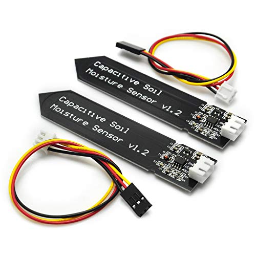
I use a standard (read: cheap) water sensor (for example: https://www.amazon.com/Gikfun-Capacitive-Corrosion-Resistant-Detection/dp/B07H3P1NRM). Just make sure it's coated or else it will corrode over time. I only need one sensor for high and low levels because it gives me an analog reading indicating much water there is.
I use a transistor for switching (instead of a relay) and a single cheapo 5V power supply that I step up to 12V for the valve.
Make sure the pressure of the water is within the range of the specs on the valve. If it's too low you might not get any flow. If it's too high, the valve will be unreliable.
Or, use a solid state relay like these: https://smile.amazon.com/Kyoto-Electric-KF0602D-Solid-State/dp/B00B888WVC/
Be careful when looking at solid state relays. Many only work with alternating current loads, not DC loads like you plan to use.
Also make sure the trigger voltage is compatible with the esp8266 3.3v outputs. Some require a 5v trigger level,
I tried this exact same setup a couple of weeks ago and was was not able to get it working until I added a logic level converter to pull up the D4 pin from 3.3V to 5V (Amazon link). The LEDs were definitely not as bright as when they were connected to a separate 5v power supply, but they did work.
I was going to buy one of those from them, but they want $13.50 for shipping on a $15 item. They seriously need some better shipping options there.
Maybe they're selling through Amazon so I'll check there.
Aliexpress has most boards for pretty much as expensive as they are in the us.
Edit: this doesn't seem too bad if I take prime shipping into account: SparkFun (PID 13907) ESP32 Thing https://www.amazon.com/dp/B01MG9BNEN/
hi, sure! I used a cheap generic "Buck Converter DC DC Step Down" referred in the amazon listing as MP1584EN, that takes max 24V IN (so we should be within the range even on charging phase) and lowers it down to 3.3v needed to run safely the esp8266.
amazon link: https://www.amazon.it/gp/product/B01MQGMOKI/ref=ppx_yo_dt_b_asin_title_o01_s00
​
on my module i have a screw for selecting the desired voltage output, you have to be very accurate, slights movements of this screw cause big changes in output, but with some patience and a multimeter you should be able to set it up for your desired OUT value.
​
as for your LDO attempt: i don't know which model you used but if it gets hot it's either too much voltage IN, hence the lowering process produces too much heat or too much amperage to sustain. Check the datasheets if you remember which model you used
Yea sounds consistent with what I read about conductive sensors :P
Check this one out; is the same that I have used
Oh, yeah, if you've already got cat5 in the walls then go with it. Worst case you might need to redo some connectors. A PoE switch and something like these and you're done.
I recently bought this ESP32 with a 4.7" E-Ink display. https://www.banggood.com/LILYGO-T5-4_7-inch-E-paper-Screen-ESP32-V3-Version-16MB-FLASH-8MB-PSRAM-WIFI-Bluetooth-Display-Module-p-1791808.html?cur_warehouse=CZ&ID=6300831&rmmds=search
So far Im really satisfied, it taking around 0.2mA in deepsleep, so the battery should last for quite long...
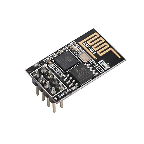
You can buy ESP-12E and solder them individually onto something like this: https://www.aliexpress.com/item/10pcs-lot-ESP8266-serial-WIFI-module-adapter-plate-Applies-to-ESP-07-ESP-08-ESP-12/32478389002.html
Otherwise, you're looking at complete boards like NodeMCU.
Check out IFTTT, and create an applet that allows you to post to a Maker channel request and send an email as a result!
Then, all you need is a simple post/get request to a special URL and you'll have an email via Gmail headed your way.
If I understand you right, you want an esp board on which you can use I2C? If so I'd recommend the Nodemcu Dev Board. It's my got to board, becuase you hava a lot of GPIOs and a voltage regulator in the board. You could also check out this dev board. It has some nice feautres like a single ws2811 LED or a photo resistor. However I never used this board.
It's relatively easy to do, but the 3.3V ESP8266 requires level shifting when talking to the normal, 5V HC-SR04. I see hookups on the Internet with no voltage translation, but doing so could fry the ESP8266 or shorten it's life.
If you haven't already purchased the sensor, buy the HC-SR04+. It's a 3.3 Volt version of the same sensor, and it also consumes less current.
If you already have the 5V version, check out this discussion, here.
I've had great success with the v2 from this seller
Openhab. The is a raspberry version and lots of work being done with esp8266 you could have what you want and more in an hour or 2 check this guy he's done a couple of good posts http://www.makeuseof.com/tag/author/jbruce/ here's the one on openhab and Pi http://www.makeuseof.com/tag/getting-started-openhab-home-automation-raspberry-pi/
I actually just installed the SDK + toolchain using this guide/makefile: https://github.com/pfalcon/esp-open-sdk#building and it went pretty smoothly. The compiler works but esptool.py (only used for flashing afaik) has an error which I haven't looked into yet. EDIT: it was using the wrong python version, easy fix
This post was very informative about how the whole thing works (bootloader/rom/flash and built in functions). So now I'm using the makefile from the blinky example to build my own first project (something simple like listen on a port and send incoming data to uart).
Kolban's book is very useful as reference for the built in functions.
I can't compare to the other platforms but haven't had major problems with this one yet. Arduino is probably easier to use and setup especially on windows.
Huh, that's interesting. I guess the easiest thing to do is use a 3.7V LiPo with one of these.
I also have this WeMos one, but it has a USB to serial converter and I'm not sure it powers down when running on battery only.
Updated! I actually bought this module a few weeks back. Assuming you adjust the potentiometer correctly to output 3.3v, is it a good solution for battery-based projects?
check this : http://bbs.espressif.com/viewtopic.php?f=7&t=1639
''' Re: SSL Authentication to AWS IOT Service Postby Espressif_Faye » Mon Jan 25, 2016 6:58 pm
Hi,
Yes, ESP8266 does not support TLS 1.2 now. Are you trying to connect "A1QQ280DDHPJDD.iot.us-east-1.amazonaws.com" ? It seems to be TLS 1.2 which ESP8266 does not support now. In your log, it is the server send an ALERT packet after ESP8266 sent SSL_CLIENT_HELLO packet. ESP8266 can connect to https://aws.amazon.com but fail to connect to the IOT server. Or you can try to check the difference between these servers. '''
Intellitext, code overview scroll bars, catching common errors and mistakes as you type, inline documentation, and power mode.
Just have a look through the packages available on atom.io
With a mesh network like PainlessMesh you can connect as many ESPs as you want, even without a wifi router. Nodes connect and disconnect dynamically as they are turned on and off. Messages are relayed from node to node through the mesh, so as long as a node can reach at least one other node, it can communicate with the whole mesh. This means the nodes can be spread out over an area that's much larger than the radio range of one ESP. It's a really great technology, and painlessMesh makes it fairly easy.
If the github page is too advanced here's a hackster article that walks you through the whole setup.
I used Libre Draw:
https://www.libreoffice.org/discover/draw/
There's probably a better way to draw component diagrams, but this is what I had and already knew how to use.
Well done! Now you can send the data to ThingSpeak or some other cloud destination.
Here https://thingspeak.com/channels/9892 is mine.
It shows only the number of pulses because it is not calibrated.
Sump Monitor. Ping sensor measures depth of water in the basement sump, ESP8266 sends results to a ThingSpeak channel so I can see how often the sump's emptying from wherever I am.
I have a check at the top of my loop () to verify WIFI is still connected and connect if not. This fixed the problem you have been experiencing. Some logging to the serial port over a multi-day run confirmed that the connect was lost randomly reconnection was needed. You will also need to put some yield () and delay () calls in your loop if it runs (blocks) for a long time. I am running a reliability test now; currently the ESP8266 has been operating continuously for over 8 days now with no resets.
Thanks.
Firstly, I've updated my write up, as its XBM not BXM. The online tool I used was: https://convertio.co/bmp-xbm/
Initially I didn't know XBM was actually a proper image format, and assumed (having looked at the various existing logos/graphic elements) that it was simply a Hex array of Black/White binary values. I spent ages converting the 40x40 B&W logo to a 40x40 grid of 1s and 0s and then converted this to pairs of Hex and dropped it into the code as a javascript array... well, it kind of worked but skewed the image - it was at this point I had a dig around and realised I'd completely over-complicated matters! :(
Didn't think about gimp, and but as I had the BMP already I just looked for an online converter.
I highly recommend these boards. There is also a 16MB (128M bits) version for a couple more dollars if you are running low on flash.
My board like this had silkscreen on the back which said 6 to 24 volts. I can confirm that with < 6 V applied the on-board regulator will not regulate down to 5V properly for the ESP.
I have indeed experienced the same with my homemade board, and I think what /u/wakeupbomb said is spot on. Tempted to trying one of these "programmers" to see if I get more consistent results.
Good find! I bought 2 from them, and 2 from here
I live in Japan and usually get stuff from ali in about 10 days, will report back once I get them.
I prefer the Wemos modules, in part because people on their forum are extremely knowledgable and helpful.
For sensors the main issues are:
a) does it work at 3.3 volts? Arduinos work at 5 volts but all of the ESP modules use 3.3 volts so your sensors need to operate at 3.3V
b) is there an Arduino library for the device and has anyone gotten it working with an ESP module. Almost all Arduino libraries work on the ESP, but there are a few exceptions.
1、WiFi module is industrial-grade chips ESP8266, which is ESP-12E with metal shield, strong anti-interference ability;
2, Shield is pin-compatible with Arduino Uno, Mega2560 and other control board. A voltage converter chip is used to deal with 3.3V (Esp8266) and 5V (Arduino);
3, Dual DIP switches is used for serial ports so that this module shield can be used alone as an Arduino Uno expansion board, and also be used as ESP8266 expansion board;
4, Serial data is transported to WiFi device transparently, and vice versa. Arduino program does not need any configuration;
5, WebServer is developed to configure WiFi parameters and serial port parameters;
6, The module shield can be used as an independent ESP8266 development board. for instance, downloading the official AT commands firmware, NodeMCU open source firmware can be used;
7, The module shield also can be used as stand-alone expansion board for Arduino Uno. See More: https://www.gitbook.com/book/fineshang/esp8266-based-serial-wifi-shield-for-arduino-user/details
You can try to create it yourself. I'm planning on doing almost the same as you.
I'm going to try my luck with http://www.pcbweb.com (free schematic and board design) and http://dirtypcbs.com (+/- 10 boards 5x5cm for $14 including shipping).
Now only to find the time to start putting it together.
Yeah, there's no way to discharge the capacitor once it's charged in that circuit, so it never resets. Something like this works though.
PlatformIO depends on awesome and irreplaceable Python-based construction tool named SCons. PlatformIO Code Builder uses it to build single source code for the multiple embedded platforms. The SCons team works on supporting Python 3. See
> This will be the last release to support Python versions earlier than 2.7, as we begin to move toward supporting Python 3.
Nevertheless, we will add support for Python 3 for the rest our features (excluding code builder).
After years of using the default Arduino IDE, I now use platformIO (VSCode extension) with Visual Studio Code IDE (so, Arduino / C++). It has intellisense, dark theme etc... much richer IDE.
Fun little boards but a pain to work with, it's easier to use the USB serial as long as it has the 3.3v option. Basics are you have to have a power jumper to ch_pd and vcc (you mentioned you already got it to power on). Have tx go to rx and rx to tx, if uploading fails try swapping them.
You have to add esp8266 from the board manager in the Arduino ide and set it as the current board. When you are ready to flash it, you have to jumper gpio 0 to ground before you plug it in, then plug it in with gpio 0 still at ground (this places it in flash mode), select the right com port and compile and upload the code. Remove the gpio 0 jumper and reset.
Always remember to use 3.3v and keep power on vcc and ch_pd.
https://www.hackster.io/ROBINTHOMAS/programming-esp8266-esp-01-with-arduino-011389
As the others have mentioned, you need to get a USB to ESP01 adapter to flash new firmware on it. I'd recommend something like this.
Steppers are from Amazon: https://smile.amazon.de/dp/B07VGV1XFT/ref=cm_sw_r_cp_apa_glt_i_K2KFNJMJZS6YBA1V5712
I made a closeup at 1:40 maybe Look at the 4k version on Youtube https://youtu.be/Rx0UTXwBU44
A simple soldering iron will do just fine. Look for something with temperature control (rather than just a dial) such as this one here
https://www.amazon.com/Soldering-Digital-Welding-Portable-Electric/dp/B08R3515SF/
Every iron comes with a selection of tips. For most electronics, a fine tip is better, but it depends on the component size.
The cover is a shadow box that I bought from Micheals. I put some printer paper inside so you cant see in but the light from the display can shine out. I got the display on amazon here, but it is a generic MAX7219 that you can find anywhere. I 3d printed a mount that hold the display in place in the case.
I'll take a picture soon and post. The nodeMCU board is this
I've read elsewhere about the power supply being "fingered" as the culprit. I am using a solar panel controller from DFRobot as the power source. Would putting a capacitor between the board and the controller help?
TIA
According to the Amazon description they certainly should be 5V :-
https://www.amazon.co.uk/gp/product/B01AU6UG70/ref=ppx_yo_dt_b_asin_title_o00_s01?ie=UTF8&psc=1
I would recommend using a USB to ESP-01 Adapter/ Programmer if you don't have one already.
https://www.amazon.com/gp/product/B07Q17XJ36/ref=ppx_yo_dt_b_search_asin_image?ie=UTF8&psc=1
I use a DC-DC power supply to power my ESPs from 12V. The simplest are something like the USB power supplies that come with a USB cable on them meant for dash cams.
https://smile.amazon.com/gp/product/B00R5JL8WI/
These are great if your ESP board is one of the ones with a USB connector. If you;re using a bare ESP8266 that needs 3.3v, then I use a DC-DC buck converter. 6 for $8!
https://smile.amazon.com/gp/product/B018JWCX8M/
These obviously work for 5V, too, but I'm lazy and like the first module which already has wires and connectors and is in a nice module already
I'm using a diymall 128x64 oled in that setup. should be a few bucks through some place like aliexpress [amazon link]
I have one of these and with a little minor soldering skills you can flash them. They aren't super bright but work pretty well. I have the AiLight firmware on them.
Smart WiFi Bulb,Weton Smart LED Bulb Multicolored Light Bulbs Work with Amazon Alexa Google Home, No Hub Required,Remote Control via Free App for Android & all Smartphones,Dimmable Light Sunrise Light https://www.amazon.com/dp/B0796RFMV3/ref=cm_sw_r_cp_apa_40DLBb49GWJS8
A passive latching relay may be what you are looking for. Here's one on Amazon. That one has a 12V coil. You might be able to find another with a lower voltage, or just a multi-cell battery. Probably 3 LiPo's would be able to pull that coil in.
Looking at the datasheet linked in the Amazon listing, the TE relay they are using does have a 5V version, but it will come without a PCB.
I use these for power on my bench. I have thought about adding fuses, just haven’t made it there yet. I just connect 4 of those, 2 to each power rail.
Mean Well LRS-50-5 Switching Power Supply, Single Output, 5V, 10A, 50W, 3.9" L x 3.23" W x 1.18" H https://www.amazon.com/dp/B019GYOCMM/ref=cm_sw_r_cp_api_i_mM0DFbGTKQA4M
Duttek (2-Pack) 50CM Dupont 10 Pin Female Header to 2 Port Dual USB 2.0 Type A Female Motherboard Extender Splitter Cable Cord (2AF/10Pin 0.5M) https://www.amazon.com/dp/B06Y5C7H19/ref=cm_sw_r_cp_api_i_AL0DFb8B14XEM
The NodeMCU board runs on 5V, not 3.3v. The most fool-proof solution would be control the misting device with a 5v relay module like the link below. Make sure that it has an opto-coupler, that allows you to connect the IO from the NodeMCU directly to the relay. The relay has its own 5v input and only uses the signal from the NodeMCU as a trigger.
Add in some larger marine shrink wrap and you are good to go.
XHF 2 inch (50mm) 3:1 Waterproof Heat Shrink Tubing Marine Grade Wire Cable Adhesive Lined Tube Insulation Seal Against Moisture Corrosion and Air Leakage, 4 Ft Clear https://www.amazon.com/dp/B07SF5FJMK/
I was lucky enough to get one at a local maker faire. I have a few part and pieces to make something close, but this had everything in one package. There is something close on Amazon https://www.amazon.com/WINGONEER-Wireless-Module-Bluetooth-Development/dp/B07RPSFMVY/
I had it originally grabbing one an hour, but changed it to get on button push.
I just always bury them about an inch, did large (several thousand plants sometimes) automated systems in Oregon for cannabis & grapes for 5 years.
There we used PVC under ground and popped it up to drippers that could be replaced if needed. But never had any clogs.
Never got them on amazon but these are very similar, everything is built in. Not sure if brown assists with algae but like I said about an inch underground is where we had them. https://www.amazon.com/100-Feet-Irrigation-Hydroponics-Dripline-Emitter/dp/B0746837DL/
Ours were half inch though for diameter. Some times beds are so small like on your balcony though that yea a turret would actually make a lot more sense lol
This could be useful. I would really like a tool that would give me -60 dBm to -30 dBm like a geiger counter, but update faster. Like the Signal Meter function on the Android App https://play.google.com/store/apps/details?id=com.farproc.wifi.analyzer&hl=en_US but that updates fast, not every 15 seconds or so like the app does, and one that tells me with some signal difference whether I'm a few feet away vs. dozens of feet away.
Are you certain it's a 1306? That looks an awful lot like my SH1106.
I was able to get mine working in micropython, though it was an 1106 display and not a 1306. https://github.com/jim-p/tnsr-display - links to my code and drivers and so on are there.
thanks for your feedback!
Adding timestamps and GPS coords to entries is a good point indeed, I'm adding your idea to the ToDo list.
The functional heap window is currently ~30Kb (130Kb heap free after init, and becomes unstable under 100Kb), it offers up to an hour of stability before the heap runs out and the ESP restarts. Without this protection the .db file eventually gets corrupted and data is lost.
Moreover, the sqlite3 implementation has a hard limit on the amount of writes you can make on a single file and produces all sort of symptoms (including data loss) over this limit.
Because of this effect, I have to choose very carefully what code/library I add until I find what's leaking memory (probably my bad code, but could also be sqlite3 or the BLE library itself).
Maybe a GATT characteristic could provide that feature too?
What's funny is that the initial motivation of this project was to replicate the ESP8266 HoBo Clock idea by using BLE services while I had absolutely no idea if it could do it.
https://developer.android.com/training/connect-devices-wirelessly/nsd.html
I haven't done DNS-SD from Android specifically, but its how I discover my devices in my Homeseer plugins. Should work identically.
Edit:
I just tested this: https://play.google.com/store/apps/details?id=com.melloware.zeroconf
It sees them, too. (I expose mine both with mDNS and DNS-SD/SDDP, I think its seeing the mDNS endpoints.
Have you tried using some kind of a wifi analyzer to see if it's really emitting something?
For instance using an app for the phone called "wifi analyzer" https://play.google.com/store/apps/details?id=com.farproc.wifi.analyzer&hl=en
or installing inssider on the laptop? http://www.inssider.com/
See if you pick up anything with them
Put down the soldering iron and and spend $15 on something like this. Required for the hobby.
Here in the US our 220v is delivered via 2 separate 110v lines, so some differences apply. Nevertheless, here's what I did to create a wifi switch for my 220v pool pump. I bought one of these, which is a 220v contactor with its own 110v relay:
https://www.amazon.com/Packard-C230B-Pole-Contactor-Voltage/dp/B001KGSJ74/ref=sr_1_3?crid=1XNJBBTZBVOTI&keywords=Packard+C230B+2+Pole+30+Amp+Contactor&qid=1671207006&s=industrial&sprefix=packard+c230b+2+pole+30+amp+contactor%2Cindustrial%2C97&sr=1-3
and wired it inline with the 220v circuit (two hots and a ground). Because I have no neutral wire on the 220v circuit, I had to run a separate 110v power circuit to power the relay. The 110v circuit is wired to a Sonoff Basic wifi switch, which then powers the relay of the contactor. The end result is that I can use my home automation network to control the Sonoff switch, which in turn controls the pool pump. Hopefully a variation of this setup specific to your needs can work.
Oooh? That's intriguing and exciting! This feels like the way to go tbh. Unfortunately, I've no experience with the Arduino, yet. I've some experience in scripting though (AutoHotKey, Auto it, very little Python, vbs and even (less) Java). Writing for Arduino seems fairly similar to AHK and Python. I've watched a lot of Great Scott! videos on YouTube and he uses Arduino extensively, it seems easy enough using an Arduino, this is why I mentioned it in my question.
Would you happen to know if I am able to accomplish this using just a single momentary switch, a relay and Arduino? I would like to make more of a passthrough-like smart outlet. My intention is to build the switch into my desk while keeping the project box out of sight, for a nice minimalist look. So I plug the LED utility light into the Arduino controlled outlet and then plug the outlet into the power strip that's on the underside of my workbench and whenever I need my light, I reach over and tap the switch to turn it on/off.
Lastly, I know that I will need 5v to power the Arduino at all times. I do not want to have a USB cable going into the project box. I only want 1 cable to power it all. How would I go about doing this? I feel that if I install a switched and fused c13 connector on the project box be ideal for sending power into the project box but am drawing a blank on how I would wire the always on power going to the 5v USB charger to power the Arduino. Would I create a piggyback connection to the c13 connector with the live wire is being ran through the relay for switching and then add a short 3 outlet power strip for the always on connection also going directly to the c13 connector?
Sorry for so many questions. I'm kinda bouncing ideas off of you here, like I said in another comment, I try to incorporate the human element in my online interactions.
With a 4F capacitor you'd get about a minute of power at 100ma. But you also need to take into account the dropout voltage of the standard linear regulator on ESP8266s so your time is going to be less (you can only reliably discharge to ~4V).
A battery option is the practical choice.
I've done this myself with my own ceiling fan. Has one switch for a light and another switch with "off, 1, 2, 3".
For that I bought:
an esp8266 (I chose a NodeMCU)
a mini power supply (I used a similar one to this one, but I'm from Germany so it's 220V. You'll have to look for the appropriate mini power supply for your country: https://www.amazon.com/EC-Buying-Step-Down-Intelligent-Switching/dp/B09Z253MQ2/)
4 relay board (this for instance: https://www.amazon.com/SunFounder-Channel-Shield-Arduino-Raspberry/dp/B00E0NSORY/)
a pack of breadboard jumper wires
Now keep in mind that your ceiling fan likely doesn't want multiple modes switches on at the same time. So one relay is of course for simply switching the light on the off.
But the second relay isn't just for the first mode but switches the hot wire. One default output you leave unconnected. The other output you connect to the input of the third relay.
The third relay's default output is then connected to the "1" mode cable of the fan. And the other output is connected to the fourth relay.
The fourth relay's default output is connected to the "2" mode cable of the fan and the other output is connected to the "3" mode cable of the fan.
That way you ensure that no two modes can be switched on at the same time.
How exactly is the garage going to open without power? Is the garage opener on a backup generator but the ESP isn't?
Apart from that if you want the ESP to not lose power first then use one of these: https://www.amazon.com/dp/B0B2WR38DH/ (Just an example and the first one I found. There are others on there.)
And the relay shouldn't switch by itself. I'm using smart plugs with ESP8266s inside which I flashed with ESPEasy and those plugs don't do anything to the relay if you power them on or off. So maybe try a different pin to switch your relay.